Header file with declarations and macros for driving an at24cm0x. More...
#include "../../../utils/macros/stringify.h"#include "../../../hal/avr0/twi/twi.h"#include "../../../utils/systick/systick.h"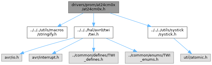
Go to the source code of this file.
Macros | |
| #define | AT24CM0X_HAL_PLATFORM avr0 |
| Sets the target platform for the AT24CM0X hardware abstraction layer (HAL), e.g., avr or avr0. | |
| #define | AT24CM0X_MEMORY_SIZE 262144UL |
| Total AT24CM0X EEPROM memory size in bytes. | |
| #define | AT24CM0X_PAGES 1024UL |
| Number of memory pages of the AT24CM0X EEPROM device. | |
| #define | AT24CM0X_PAGE_SIZE 256UL |
| Size of a single EEPROM page in bytes. | |
| #define | AT24CM0X_ENABLE_INTEGRITY_CHECK |
| Enables additional data integrity checks for EEPROM transfers. | |
| #define | AT24CM0X_WRITE_ACKNOWLEDGE_POLLING |
| Enables write acknowledge polling after EEPROM write operations. | |
| #define | AT24CM0X_BASE_ADDRESS 0x50 |
| Base I2C address of the AT24CM0X EEPROM device. | |
| #define | AT24CM0X_ADDRESS_MASK 0x04 |
| Mask for hardware address pin bits within the I2C address. | |
| #define | AT24CM0X_ADDRESS_HIGH_MASK 0x03 |
| Mask for high-order address bits used for bank selection. | |
| #define | AT24CM0X_MULTI_DEVICES |
| Enables support for multiple AT24CM0X devices on the I2C bus. | |
| #define | AT24CM0X_WP_CONTROL_EN |
| Enables software control of the EEPROM write-protect (WP) feature. | |
| #define | AT24CM0X_WRITE_CYCLE_MS 10UL |
| Write cycle time of the AT24CM0X device in milliseconds. | |
Typedefs | |
| typedef enum AT24CM0X_WP_Mode_t | AT24CM0X_WP_Mode |
| Alias for enum AT24CM0X_WP_Mode_t representing WP control modes. | |
| typedef enum AT24CM0X_Status_t | AT24CM0X_Status |
| Alias for enum AT24CM0X_Status_t representing driver status codes. | |
Enumerations | |
| enum | AT24CM0X_WP_Mode_t { AT24CM0X_WP_Mode_Enabled = 0 , AT24CM0X_WP_Mode_Disabled } |
| Specifies the write-protect mode for the AT24CM0X device. More... | |
| enum | AT24CM0X_Status_t { AT24CM0X_Status_Done = 0 , AT24CM0X_Status_Address_Error , AT24CM0X_Status_Page_Error , AT24CM0X_Status_Size_Error , AT24CM0X_Status_Data_Error , AT24CM0X_Status_TWI_Error , AT24CM0X_Status_General_Error } |
| Status codes returned by AT24CM0X driver operations. More... | |
Functions | |
| void | at24cm0x_init (void) |
| Initializes the AT24CM0X EEPROM driver. | |
| void | at24cm0x_device (unsigned char identifier) |
| Selects the active AT24CM0X device. | |
| void | at24cm0x_wp (AT24CM0X_WP_Mode mode) |
| AT24CM0X_Status | at24cm0x_write_byte (unsigned long address, unsigned char data) |
| Writes a single byte to the AT24CM0X EEPROM. | |
| AT24CM0X_Status | at24cm0x_write_page (unsigned int page, unsigned char *data, unsigned int size) |
| Writes a sequence of bytes to a single EEPROM page. | |
| AT24CM0X_Status | at24cm0x_read_current_byte (unsigned char *data) |
| Reads the current byte from the AT24CM0X EEPROM. | |
| AT24CM0X_Status | at24cm0x_read_byte (unsigned long address, unsigned char *data) |
| Reads a single byte from the AT24CM0X EEPROM. | |
| AT24CM0X_Status | at24cm0x_read_sequential (unsigned long address, unsigned char *data, unsigned int size) |
| Reads a sequence of bytes from the AT24CM0X EEPROM. | |
Detailed Description
Header file with declarations and macros for driving an at24cm0x.
This file provides function prototypes, type definitions, and constants for communication with an at24cm0x eeprom chip.
- Date
- 2026-01-24
- Version
- 1.0 Release
- Copyright
- Copyright (c) 2026 g.raf Released under the GPLv3 License. (see LICENSE in repository)
- Note
- This file is part of a larger project and subject to the license specified in the repository. For updates and the complete revision history, see the GitHub repository.
- See also
- https://github.com/0x007e/drivers-prom-at24cm0x "AT24CM0X eeprom driver library"
Macro Definition Documentation
◆ AT24CM0X_ADDRESS_HIGH_MASK
| #define AT24CM0X_ADDRESS_HIGH_MASK 0x03 |
Mask for high-order address bits used for bank selection.
This macro defines the bit mask used to encode or decode high-order memory address bits that are mapped into the I2C address for larger AT24CM0X devices. The mask depends on the configured memory size.
- Note
- For devices smaller than 2 Mbit (AT24CM0X_MEMORY_SIZE < 262144UL), the value 0x01 enables a single high-order address bit. For 2 Mbit devices and above, the value 0x03 enables two high-order address bits for multiple banks.
◆ AT24CM0X_ADDRESS_MASK
| #define AT24CM0X_ADDRESS_MASK 0x04 |
Mask for hardware address pin bits within the I2C address.
This macro defines the bit mask used to apply or extract the hardware address pin bits (such as A2/A1) to/from the AT24CM0X I2C address. The mask depends on the configured memory size.
- Note
- For devices smaller than 2 Mbit (AT24CM0X_MEMORY_SIZE < 262144UL), the value 0x06 covers the A2 and A1 bits. For 2 Mbit devices and above, the value 0x04 only covers the A2 bit.
◆ AT24CM0X_BASE_ADDRESS
| #define AT24CM0X_BASE_ADDRESS 0x50 |
Base I2C address of the AT24CM0X EEPROM device.
This macro defines the 7-bit base address used by the AT24CM0X on the I2C bus before applying any address pin or bank-dependent bits.
- Note
- The default value 0x50 is commonly used for I2C EEPROM devices.
◆ AT24CM0X_ENABLE_INTEGRITY_CHECK
| #define AT24CM0X_ENABLE_INTEGRITY_CHECK |
Enables additional data integrity checks for EEPROM transfers.
When this macro is defined, the driver can perform extra verification steps (such as consistency or bounds checks) on read and write operations to improve robustness.
- Note
- By default this macro is commented out, meaning integrity checks are disabled to minimize overhead. Uncomment or define it as a global compiler symbol to enable integrity checking in the driver.
◆ AT24CM0X_HAL_PLATFORM
| #define AT24CM0X_HAL_PLATFORM avr0 |
Sets the target platform for the AT24CM0X hardware abstraction layer (HAL), e.g., avr or avr0.
Define this macro with the name of the target platform to select the corresponding platform-specific HAL implementation (such as TWI communication functions) for the AT24CM0X EEPROM driver. Common values are avr (classic AVR architecture) or avr0 (AVR0/1 series).
- Note
- Set this macro as a global compiler symbol to ensure that the correct HAL implementation is used across the entire project.
◆ AT24CM0X_MEMORY_SIZE
| #define AT24CM0X_MEMORY_SIZE 262144UL |
Total AT24CM0X EEPROM memory size in bytes.
This macro defines the overall storage capacity of the AT24CM0X device and is used for address calculations and for validating the accessible address range for read and write operations within the driver.
- Note
- The default value 262144UL corresponds to a 2 Mbit (256 KB) EEPROM. Adjust this value to match the actual device variant in use (for example, 131072UL for 1 Mbit).
◆ AT24CM0X_MULTI_DEVICES
| #define AT24CM0X_MULTI_DEVICES |
Enables support for multiple AT24CM0X devices on the I2C bus.
When this macro is defined, the driver provides mechanisms to select and address more than one AT24CM0X device, distinguished by their I2C address or identifier.
- Note
- By default this macro is commented out, meaning the driver operates with a single EEPROM device instance. Uncomment or define it as a global compiler symbol to enable multi-device support.
◆ AT24CM0X_PAGE_SIZE
| #define AT24CM0X_PAGE_SIZE 256UL |
Size of a single EEPROM page in bytes.
This macro defines how many bytes are contained in one memory page of the AT24CM0X device. It is used for page boundary calculations and for validating buffer sizes in page write operations.
- Note
- The default value 256UL corresponds to 256 bytes per page. Adjust this value if a device with a different page size is used.
◆ AT24CM0X_PAGES
| #define AT24CM0X_PAGES 1024UL |
Number of memory pages of the AT24CM0X EEPROM device.
This macro defines how many pages the EEPROM memory is divided into. It is used for page-based addressing and validation in page write and page read operations within the driver.
- Note
- The default value 1024UL corresponds to 1024 pages in total. Make sure this value matches the actual page layout of the selected device.
◆ AT24CM0X_WP_CONTROL_EN
| #define AT24CM0X_WP_CONTROL_EN |
Enables software control of the EEPROM write-protect (WP) feature.
When this macro is defined, the driver provides an interface to control the WP state via at24cm0x_wp, so that write access to the device can be enabled or disabled in software.
- Note
- By default this macro is disabled, in cause of WP pin is permanently tied to a fixed level in hardware.
◆ AT24CM0X_WRITE_ACKNOWLEDGE_POLLING
| #define AT24CM0X_WRITE_ACKNOWLEDGE_POLLING |
Enables write acknowledge polling after EEPROM write operations.
When this macro is defined, the driver performs acknowledge polling after a write operation to the AT24CM0X device, repeatedly checking for the device's ACK to determine when the internal write cycle has completed. This can reduce overall write latency by allowing the driver to proceed as soon as the device has completed.
- Note
- By default this macro is commented out, so acknowledge polling is disabled and the driver must rely on fixed write cycle delays. Uncomment or define it as a global compiler symbol to enable acknowledge polling.
◆ AT24CM0X_WRITE_CYCLE_MS
| #define AT24CM0X_WRITE_CYCLE_MS 10UL |
Write cycle time of the AT24CM0X device in milliseconds.
This macro defines the typical time required by the EEPROM to complete an internal write cycle after a write operation has been issued.
- Note
- The default value 10UL represents a 10 ms write cycle time, which is commonly specified for AT24-series EEPROMs. Adjust this value if the datasheet of the specific device variant indicates a different timing.
Typedef Documentation
◆ AT24CM0X_Status
| typedef enum AT24CM0X_Status_t AT24CM0X_Status |
Alias for enum AT24CM0X_Status_t representing driver status codes.
◆ AT24CM0X_WP_Mode
| typedef enum AT24CM0X_WP_Mode_t AT24CM0X_WP_Mode |
Alias for enum AT24CM0X_WP_Mode_t representing WP control modes.
Enumeration Type Documentation
◆ AT24CM0X_Status_t
| enum AT24CM0X_Status_t |
Status codes returned by AT24CM0X driver operations.
This enumeration defines the possible result codes for EEPROM operations such as initialization, read, and write functions in the AT24CM0X driver.
◆ AT24CM0X_WP_Mode_t
| enum AT24CM0X_WP_Mode_t |
Specifies the write-protect mode for the AT24CM0X device.
This enumeration defines the possible states of the EEPROM write-protect (WP) control as used by the AT24CM0X driver.
| Enumerator | |
|---|---|
| AT24CM0X_WP_Mode_Enabled | Write-protect enabled, write access is blocked. |
| AT24CM0X_WP_Mode_Disabled | Write-protect disabled, write access is allowed. |
Function Documentation
◆ at24cm0x_device()
| void at24cm0x_device | ( | unsigned char | identifier | ) |
Selects the active AT24CM0X device.
This function updates the internal device identifier used by the AT24CM0X driver to communicate with a specific EEPROM device on the I2C bus. The given identifier is masked with the configured AT24CM0X_ADDRESS_MASK and combined with AT24CM0X_BASE_ADDRESS to form the effective 7-bit I2C address stored in the internal at24cm0x_device_identifier.
- Parameters
-
identifier Device selector value used to derive the target AT24CM0X I2C address.
◆ at24cm0x_init()
| void at24cm0x_init | ( | void | ) |
Initializes the AT24CM0X EEPROM driver.
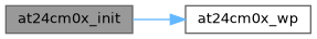
This function initializes the internal configuration of the AT24CM0X driver. If write-protect control is enabled at compile time (AT24CM0X_WP_CONTROL_EN), it first activates write-protect by calling at24cm0x_wp with AT24CM0X_WP_Mode_Enabled. It then sets the internal device identifier used for I2C communication to either AT24CM0X_BASE_ADDRESS when multi-device support is enabled (AT24CM0X_MULTI_DEVICES), or to AT24CM0X_ADDRESS when operating in single-device mode.
- Note
- This function should be called once during system startup before any AT24CM0X read or write operations are performed.
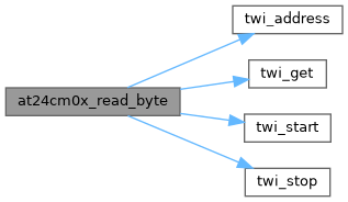
◆ at24cm0x_read_byte()
| AT24CM0X_Status at24cm0x_read_byte | ( | unsigned long | address, |
| unsigned char * | data ) |
Reads a single byte from the AT24CM0X EEPROM.
This function reads one byte of data from the specified EEPROM address of the AT24CM0X device. It first checks whether the given address is within the valid memory range defined by AT24CM0X_MEMORY_SIZE; if not, it returns AT24CM0X_Status_Address_Error.
The read operation is performed using a random-read sequence: a start condition is sent, the target address is set via at24cm0x_send_address, and a stop condition is issued. Then a repeated start is generated, the device is addressed in read mode using the current at24cm0x_device_identifier, and a single byte is read with twi_get, followed by a stop condition.
If any TWI communication error occurs, the function returns AT24CM0X_Status_TWI_Error. On success, the received byte is stored at the location pointed to by data and the function returns AT24CM0X_Status_Done.
- Parameters
-
address EEPROM memory address from which the byte will be read. data Pointer to a byte where the received data will be stored.
- Returns
- AT24CM0X_Status Status code indicating the result of the operation.

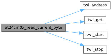
◆ at24cm0x_read_current_byte()
| AT24CM0X_Status at24cm0x_read_current_byte | ( | unsigned char * | data | ) |
Reads the current byte from the AT24CM0X EEPROM.
This function reads the byte currently addressed by the AT24CM0X internal address counter using a TWI/I2C read operation. It sends a start condition, addresses the device in read mode using the internally stored at24cm0x_device_identifier, reads one byte into the provided buffer, and then issues a stop condition.
If any TWI communication error occurs during the sequence, the function returns AT24CM0X_Status_TWI_Error. On success, the received byte is stored at the location pointed to by data and the function returns AT24CM0X_Status_Done.
- Parameters
-
data Pointer to a byte where the received data will be stored.
- Returns
- AT24CM0X_Status Status code indicating the result of the operation.
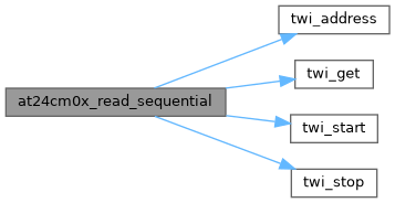
◆ at24cm0x_read_sequential()
| AT24CM0X_Status at24cm0x_read_sequential | ( | unsigned long | address, |
| unsigned char * | data, | ||
| unsigned int | size ) |
Reads a sequence of bytes from the AT24CM0X EEPROM.
This function reads a contiguous block of data starting at the specified EEPROM address of the AT24CM0X device. It first verifies that the start address is within the valid memory range defined by AT24CM0X_MEMORY_SIZE; if not, it returns AT24CM0X_Status_Address_Error. If the requested size is zero, it returns AT24CM0X_Status_Size_Error.
The read operation is performed using a random-read followed by a sequential read: a start condition is sent, the target address is set via at24cm0x_send_address, and a stop condition is issued. Then a repeated start is generated, the device is addressed in read mode using the current at24cm0x_device_identifier, and size bytes are read into the buffer pointed to by data. All bytes except the last are read with an ACK; the final byte is read with NACK to terminate the transfer, followed by a stop condition.
If any TWI communication error occurs, the function returns AT24CM0X_Status_TWI_Error. On success, the received data block is stored in the provided buffer and the function returns AT24CM0X_Status_Done.
- Parameters
-
address Start EEPROM memory address from which the data will be read. data Pointer to the buffer where the received data will be stored. size Number of bytes to read; must be greater than 0.
- Returns
- AT24CM0X_Status Status code indicating the result of the operation.

◆ at24cm0x_wp()
| void at24cm0x_wp | ( | AT24CM0X_WP_Mode | mode | ) |
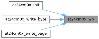
◆ at24cm0x_write_byte()
| AT24CM0X_Status at24cm0x_write_byte | ( | unsigned long | address, |
| unsigned char | data ) |
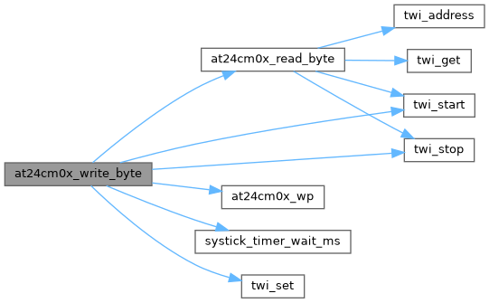
Writes a single byte to the AT24CM0X EEPROM.
This function writes one byte of data to the specified EEPROM address of the AT24CM0X device. It first checks whether the given address is within the valid memory range defined by AT24CM0X_MEMORY_SIZE; if not, it returns AT24CM0X_Status_Address_Error. If write-protect control is enabled (AT24CM0X_WP_CONTROL_EN), the function temporarily disables write-protect before issuing the write and re-enables it afterward. The write operation itself is performed using the TWI/I2C interface: a start condition is sent, the device/address sequence is transmitted via at24cm0x_send_address, the data byte is written, and a stop condition is generated.
After the write, the function either performs write acknowledge polling (AT24CM0X_WRITE_ACKNOWLEDGE_POLLING) or waits for a fixed write cycle time (AT24CM0X_WRITE_CYCLE_MS), depending on the compile-time configuration. If any TWI communication error occurs, it returns AT24CM0X_Status_TWI_Error.
When integrity checking is enabled (AT24CM0X_ENABLE_INTEGRITY_CHECK), the function reads back the byte using at24cm0x_read_byte and compares it with the original value; if they do not match, it returns AT24CM0X_Status_Data_Error. On success, the function returns AT24CM0X_Status_Done.
- Parameters
-
address EEPROM memory address at which the byte will be written. data Data byte to write to the specified address.
- Returns
- AT24CM0X_Status Status code indicating the result of the operation.
◆ at24cm0x_write_page()
| AT24CM0X_Status at24cm0x_write_page | ( | unsigned int | page, |
| unsigned char * | data, | ||
| unsigned int | size ) |
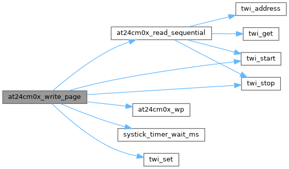
Writes a sequence of bytes to a single EEPROM page.
This function writes a contiguous block of data to one page of the AT24CM0X EEPROM. It first validates the page index against AT24CM0X_PAGES and the data length against AT24CM0X_PAGE_SIZE; if the page is out of range, it returns AT24CM0X_Status_Page_Error, and if the size is zero or not within the allowed page size, it returns AT24CM0X_Status_Size_Error.
The target EEPROM address is calculated from the page index and AT24CM0X_PAGE_SIZE. If write-protect control is enabled (AT24CM0X_WP_CONTROL_EN), write-protect is temporarily disabled before the TWI/I2C transfer and re-enabled afterward. The function then issues a start condition, sends the device/address sequence via at24cm0x_send_address, and transmits each byte from the provided buffer using twi_set, followed by a stop condition.
After the write operation, the function either performs write acknowledge polling (AT24CM0X_WRITE_ACKNOWLEDGE_POLLING) or waits for a fixed write cycle time (AT24CM0X_WRITE_CYCLE_MS), depending on the compile-time configuration. If any TWI error is detected, it returns AT24CM0X_Status_TWI_Error.
When integrity checking is enabled (AT24CM0X_ENABLE_INTEGRITY_CHECK), the function reads back the written data using at24cm0x_read_sequential into a temporary buffer and compares it byte-by-byte with the original data. If any mismatch is found, it returns AT24CM0X_Status_Data_Error. On success, the function returns AT24CM0X_Status_Done.
- Parameters
-
page Page index to write, in the range [0, AT24CM0X_PAGES - 1]. data Pointer to the buffer containing the data to be written. size Number of bytes to write; must be greater than 0 and less than AT24CM0X_PAGE_SIZE.
- Returns
- AT24CM0X_Status Status code indicating the result of the operation.