Header file with declarations and macros for driving an mcp7940. More...
#include "../../../core_types/format/time.h"#include "../../../utils/systick/systick.h"#include "../../../utils/time/validate.h"#include "../../../utils/macros/stringify.h"#include "../../../hal/avr0/twi/twi.h"
Go to the source code of this file.
Macros | |
| #define | MCP7940_HAL_PLATFORM avr0 |
| Sets the target platform for the MCP7940 hardware abstraction layer (HAL), e.g., avr or avr0. | |
| #define | MCP7940_ADDRESS 0x6F |
| Defines the TWI/I2C address of the MCP7940 device. | |
| #define | MCP7940_USE_EXTOSC |
| Selects external clock input mode for the MCP7940 RTC device. | |
| #define | MCP7940_BATTERY_BACKUP_EN |
| Enables battery backup operation and power-fail time-stamping in the MCP7940 RTC. | |
| #define | MCP7940_MFP_MODE_OUTPUT 0x00 |
| #define | MCP7940_MFP_MODE_SQUARE_WAVE 0x01 |
| #define | MCP7940_MFP_MODE_ALARM 0x02 |
| #define | MCP7940_MFP_MODE MCP7940_MFP_MODE_OUTPUT |
| Selects the operating mode of the MCP7940 multi-function pin (MFP). | |
| #define | MCP7940_MFP_SQUARE_WAVE_PRESCALER MCP7940_SQWFS_1HZ |
| Selects the output frequency of the MCP7940 square-wave signal on the MFP pin. | |
| #define | MCP7940_MFP_ALARM_MODE_ALM0 (MCP7940_ALM0EN_bm) |
| #define | MCP7940_MFP_ALARM_MODE_ALM1 (MCP7940_ALM1EN_bm) |
| #define | MCP7940_MFP_ALARM_MODE_BOTH (MCP7940_ALM1EN_bm | MCP7940_ALM0EN_bm) |
| #define | MCP7940_MFP_ALARM_MODE MCP7940_MFP_ALARM_MODE_BOTH |
| Selects which RTC alarm sources can assert the MCP7940 multi-function pin (MFP). | |
| #define | MCP7940_MFP_ALARM_POLARITY_NORMAL 0x00 |
| #define | MCP7940_MFP_ALARM_POLARITY_INVERTED RTC_ALMPOL_bm |
| #define | MCP7940_MFP_ALARM1_POLARITY MCP7940_MFP_ALARM_POLARITY_NORMAL |
| Configures the output polarity of the MCP7940 multi-function pin (MFP) when driven by Alarm 1 events. | |
| #define | MCP7940_MFP_ALARM2_POLARITY MCP7940_MFP_ALARM_POLARITY_NORMAL |
| Configures the output polarity of the MCP7940 multi-function pin (MFP) when driven by Alarm 2 events. | |
| #define | MCP7940_IO_TIMEOUT_MS 1 |
| Specifies the I/O timeout for MCP7940 bus operations in milliseconds. | |
| #define | MCP7940_OSC_ENABLE_MS 1000UL |
| Delay time in milliseconds before oscillator run check after enabling the MCP7940 oscillator. | |
| #define | MCP7940_RTCSEC 0x00 |
| Address of the MCP7940 RTC seconds register. | |
| #define | MCP7940_ST_bm 0x80 |
| #define | MCP7940_SECTEN_bm 0x70 |
| #define | MCP7940_SECTEN_bp 4 |
| #define | MCP7940_RTCMIN 0x01 |
| Address of the MCP7940 RTC minutes register. | |
| #define | MCP7940_MINTEN_bm 0x70 |
| #define | MCP7940_MINTEN_bp 4 |
| #define | MCP7940_RTCHOUR 0x02 |
| Address of the MCP7940 RTC hours register. | |
| #define | MCP7940_FORMAT_bm 0x40 |
| #define | MCP7940_HRTEN_bm 0x30 |
| #define | MCP7940_HRTEN_bp 4 |
| #define | MCP7940_RTCWKDAY 0x03 |
| Address of the MCP7940 RTC weekday register. | |
| #define | MCP7940_OSCRUN_bm 0x20 |
| #define | MCP7940_PWRFAIL_bm 0x10 |
| #define | MCP7940_VBATEN_bm 0x08 |
| #define | MCP7940_WKDAY_bp 0 |
| #define | MCP7940_RTCDATE 0x04 |
| Address of the MCP7940 RTC date (day-of-month) register. | |
| #define | MCP7940_DATETEN_bm 0x30 |
| #define | MCP7940_DATETEN_bp 4 |
| #define | MCP7940_RTCMTH 0x05 |
| Address of the MCP7940 RTC month register. | |
| #define | MCP7940_LPYR_bm 0x20 |
| #define | MCP7940_MTHTEN_bm 0x10 |
| #define | MCP7940_LPYR_bp 5 |
| #define | MCP7940_MTHTEN_bp 4 |
| #define | MCP7940_RTCYEAR 0x06 |
| Address of the MCP7940 RTC year register. | |
| #define | MCP7940_YRTEN_bm 0xF0 |
| #define | MCP7940_YRTEN_bp 4 |
| #define | MCP7940_CONTROL 0x07 |
| Address of the MCP7940 RTC control register. | |
| #define | MCP7940_OUT_bm 0x80 |
| #define | MCP7940_SQWEN_bm 0x40 |
| #define | MCP7940_ALM1EN_bm 0x20 |
| #define | MCP7940_ALM0EN_bm 0x10 |
| #define | MCP7940_EXTOSC_bm 0x08 |
| #define | MCP7940_CSTRIM_bm 0x04 |
| #define | MCP7940_SQWFS1_bm 0x02 |
| #define | MCP7940_SQWFS0_bm 0x01 |
| #define | MCP7940_SQWFS_32768HZ (MCP7940_SQWFS1_bm | MCP7940_SQWFS0_bm) |
| #define | MCP7940_SQWFS_8192HZ MCP7940_SQWFS1_bm |
| #define | MCP7940_SQWFS_4096HZ MCP7940_SQWFS0_bm |
| #define | MCP7940_SQWFS_1HZ 0x00 |
| #define | MCP7940_OSCTRIM 0x08 |
| Address of the MCP7940 oscillator trim register. | |
| #define | MCP7940_SIGN_bm 0x80 |
| #define | MCP7940_WEEKDAY_MONDAY_gc 0x00 |
| #define | MCP7940_WEEKDAY_TUESDAY_gc 0x01 |
| #define | MCP7940_WEEKDAY_WEDNESDAY_gc 0x02 |
| #define | MCP7940_WEEKDAY_THURSDAY_gc 0x03 |
| #define | MCP7940_WEEKDAY_FRIDAY_gc 0x04 |
| #define | MCP7940_WEEKDAY_SATURDAY_gc 0x05 |
| #define | MCP7940_WEEKDAY_SUNDAY_gc 0x06 |
| #define | MCP7940_ALM_SECTEN_bp 4 |
| #define | MCP7940_ALM_SECONE_bp 0 |
| #define | MCP7940_ALM0SEC 0x0A |
| Address of the MCP7940 Alarm 0 seconds register. | |
| #define | MCP7940_ALM1SEC 0x11 |
| Address of the MCP7940 Alarm 1 seconds register. | |
| #define | MCP7940_ALM_MINTEN_bp 4 |
| #define | MCP7940_ALM_MINONE_bp 0 |
| #define | MCP7940_ALM0MIN 0x0B |
| Address of the MCP7940 Alarm 0 minutes register. | |
| #define | MCP7940_ALM1MIN 0x12 |
| Address of the MCP7940 Alarm 1 minutes register. | |
| #define | MCP7940_ALM_FORMAT_bm 0x40 |
| #define | MCP7940_ALM_HRTEN_bp 4 |
| #define | MCP7940_ALM_HRONE_bp 0 |
| #define | MCP7940_ALM0HOUR 0x0C |
| Address of the MCP7940 Alarm 0 hours register. | |
| #define | MCP7940_ALM1HOUR 0x13 |
| Address of the MCP7940 Alarm 1 hours register. | |
| #define | MCP7940_ALARM_ALMPOL_bm 0x80 |
| #define | MCP7940_ALARM_ALMMSK2_bm 0x40 |
| #define | MCP7940_ALARM_ALMMSK1_bm 0x20 |
| #define | MCP7940_ALARM_ALMMSK0_bm 0x10 |
| #define | MCP7940_ALARM_ALMIF_bm 0x08 |
| #define | MCP7940_ALARM_WKDAY_bp 0 |
| #define | MCP7940_ALARM_ALMMSK_bp 4 |
| #define | MCP7940_ALARM_SECOND_MATCH_gc (0x00<<MCP7940_ALARM_ALMMSK_bp) |
| #define | MCP7940_ALARM_MINUTE_MATCH (0x01<<MCP7940_ALARM_ALMMSK_bp) |
| #define | MCP7940_ALARM_HOUR_MATCH (0x02<<MCP7940_ALARM_ALMMSK_bp) |
| #define | MCP7940_ALARM_DAY_MATCH (0x03<<MCP7940_ALARM_ALMMSK_bp) |
| #define | MCP7940_ALARM_DATE_MATCH (0x04<<MCP7940_ALARM_ALMMSK_bp) |
| #define | MCP7940_ALARM_FULL_MATCH (0x07<<MCP7940_ALARM_ALMMSK_bp) |
| #define | MCP7940_ALM0WKDAY 0x0D |
| Address of the MCP7940 Alarm 0 weekday register. | |
| #define | MCP7940_ALM1WKDAY 0x14 |
| Address of the MCP7940 Alarm 1 weekday register. | |
| #define | MCP7940_ALM_DATETEN_bp 4 |
| #define | MCP7940_ALM_DATEONE_bp 0 |
| #define | MCP7940_ALM0DATE 0x0E |
| Address of the MCP7940 Alarm 0 date (day-of-month) register. | |
| #define | MCP7940_ALM1DATE 0x15 |
| Address of the MCP7940 Alarm 1 date (day-of-month) register. | |
| #define | MCP7940_ALM_MTHTEN_bp 4 |
| #define | MCP7940_ALM_MTHONE_bp 0 |
| #define | MCP7940_ALM0MTH 0x0F |
| Address of the MCP7940 Alarm 0 month register. | |
| #define | MCP7940_ALM1MTH 0x16 |
| Address of the MCP7940 Alarm 1 month register. | |
| #define | MCP7940_PWRDNMIN 0x18 |
| Address of the MCP7940 power-down minutes timestamp register. | |
| #define | MCP7940_PWRUPMIN 0x1C |
| Address of the MCP7940 power-up minutes timestamp register. | |
| #define | MCP7940_PWRDNHOUR 0x19 |
| Address of the MCP7940 power-down hours timestamp register. | |
| #define | MCP7940_PWRUPHOUR 0x1D |
| Address of the MCP7940 power-up hours timestamp register. | |
| #define | MCP7940_PWRDNDATE 0x1A |
| Address of the MCP7940 power-down date (day-of-month) timestamp register. | |
| #define | MCP7940_PWRUPDATE 0x1E |
| Address of the MCP7940 power-up date (day-of-month) timestamp register. | |
| #define | MCP7940_PWRWEEKDAY_bp 5 |
| #define | MCP7940_PWRDNMTH 0x1B |
| Address of the MCP7940 power-down month timestamp register. | |
| #define | MCP7940_PWRUPMTH 0x1F |
| Address of the MCP7940 power-up month timestamp register. | |
Typedefs | |
| typedef enum MCP7940_Status_t | MCP7940_Status |
| Alias for enum MCP7940_Status_t representing MCP7940 RTC status flags. | |
| typedef enum MCP7940_Error_t | MCP7940_Error |
| Alias for enum MCP7940_Error_t representing MCP7940 driver error codes. | |
| typedef enum MCP7940_Mode_t | MCP7940_Mode |
| Alias for enum MCP7940_Mode_t representing MCP7940 enable/disable modes. | |
| typedef enum MCP7940_Trim_t | MCP7940_Trim |
| Alias for enum MCP7940_Trim_t representing MCP7940 trim direction selection. | |
| typedef enum MCP7940_LeapYear_t | MCP7940_LeapYear |
| Alias for enum MCP7940_LeapYear_t representing MCP7940 leap year status. | |
| typedef enum MCP7940_Register_t | MCP7940_Register |
| Alias for enum MCP7940_Register_t representing MCP7940 register block selections. | |
Enumerations | |
| enum | MCP7940_Status_t { MCP7940_Status_None = 0x00 , MCP7940_Status_Battery_Enabled = 0x08 , MCP7940_Status_Power_Fail = 0x10 , MCP7940_Status_Oscillator_Running = 0x20 } |
| Represents status and configuration flags of the MCP7940 RTC. More... | |
| enum | MCP7940_Error_t { MCP7940_Error_None = 0 , MCP7940_Error_Fail } |
| Represents error conditions reported by the MCP7940 driver. More... | |
| enum | MCP7940_Mode_t { MCP7940_Mode_Disable = 0 , MCP7940_Mode_Enable } |
| Selects enabled or disabled mode for MCP7940 features. More... | |
| enum | MCP7940_Trim_t { MCP7940_Trim_Substract = 0 , MCP7940_Trim_Add } |
| Selects the trim direction for MCP7940 oscillator calibration. More... | |
| enum | MCP7940_LeapYear_t { MCP7940_LeapYear_False = 0 , MCP7940_LeapYear_True } |
| Indicates whether the MCP7940 calendar year is a leap year. More... | |
| enum | MCP7940_Register_t { MCP7940_Register_Current_Time = 0 , MCP7940_Register_Power_Down_Time , MCP7940_Register_Power_Up_Time } |
| Selects MCP7940 time-stamp register blocks for access operations. More... | |
Functions | |
| void | mcp7940_init (void) |
| Initializes the MCP7940 RTC with battery backup, MFP mode, and oscillator settings. | |
| MCP7940_Error | mcp7940_trimming (MCP7940_Trim mode, unsigned char value) |
| Configures the MCP7940 oscillator trimming value and verifies the write. | |
| void | mcp7940_oscillator (MCP7940_Mode mode) |
| Enables or disables the MCP7940 RTC oscillator or external clock input. | |
| MCP7940_Status | mcp7940_status (void) |
| Reads and returns the current MCP7940 status flags from the weekday register. | |
| void | mcp7940_mfp_output (MCP7940_Mode output) |
| Controls the MCP7940 MFP pin when configured as a general-purpose output. | |
| const char * | mcp7940_weekday_string (unsigned char day) |
| Returns a three-letter weekday abbreviation for a given day value. | |
| unsigned char | mcp7940_weekday (MCP7940_Register data) |
| Reads the weekday value from the MCP7940 for the selected timestamp register set. | |
| void | mcp7940_time (FORMAT_Time *time, MCP7940_Register reg) |
| Reads hour, minute, and second fields from the MCP7940 into a FORMAT_Time structure. | |
| void | mcp7940_date (FORMAT_Date *date, MCP7940_Register reg) |
| Reads day, month, and year fields from the MCP7940 into a FORMAT_Date structure. | |
| void | mcp7940_datetime (FORMAT_DateTime *datetime, MCP7940_Register reg) |
| Reads both time and date from the MCP7940 into a FORMAT_DateTime structure. | |
| MCP7940_LeapYear | mcp7940_leapyear (void) |
| Returns the current leap year status from the MCP7940 device. | |
| MCP7940_Error | mcp7940_setweekday (unsigned char weekday) |
| Sets the MCP7940 weekday field in the RTCWKDAY register. | |
| MCP7940_Error | mcp7940_settime (const FORMAT_Time *time) |
| Sets the current time of the MCP7940 RTC from a FORMAT_Time structure. | |
| MCP7940_Error | mcp7940_setdate (const FORMAT_Date *date) |
| Sets the current calendar date of the MCP7940 RTC from a FORMAT_Date structure. | |
| MCP7940_Error | mcp7940_setdatetime (const FORMAT_DateTime *datetime) |
| Sets the current MCP7940 date and time from a FORMAT_DateTime structure. | |
Detailed Description
Header file with declarations and macros for driving an mcp7940.
This file provides function prototypes, type definitions, and constants for communication with an mcp7940 rtc chip.
- Date
- 2026-02-13
- Version
- 1.0 Release
- Copyright
- Copyright (c) 2026 g.raf Released under the GPLv3 License. (see LICENSE in repository)
- Note
- This file is part of a larger project and subject to the license specified in the repository. For updates and the complete revision history, see the GitHub repository.
- See also
- https://github.com/0x007e/drivers-rtc-mcp7940 "MCP7940 RTC driver library"
Macro Definition Documentation
◆ MCP7940_ADDRESS
| #define MCP7940_ADDRESS 0x6F |
Defines the TWI/I2C address of the MCP7940 device.
This macro specifies the 7-bit I2C slave address used to communicate with the MCP7940 device on the TWI/I2C bus. The value can be overridden by defining MCP7940_ADDRESS before including this header if the hardware configuration uses a different address.
- Note
- By default, MCP7940_ADDRESS is set to 0x6F.
◆ MCP7940_ALARM_ALMIF_bm
| #define MCP7940_ALARM_ALMIF_bm 0x08 |
Bit mask for the ALMIF flag indicating that an alarm event has occurred.
◆ MCP7940_ALARM_ALMMSK0_bm
| #define MCP7940_ALARM_ALMMSK0_bm 0x10 |
Bit mask for the ALMMSK0 bit, part of the alarm match mask field.
◆ MCP7940_ALARM_ALMMSK1_bm
| #define MCP7940_ALARM_ALMMSK1_bm 0x20 |
Bit mask for the ALMMSK1 bit, part of the alarm match mask field.
◆ MCP7940_ALARM_ALMMSK2_bm
| #define MCP7940_ALARM_ALMMSK2_bm 0x40 |
Bit mask for the ALMMSK2 bit, part of the alarm match mask field.
◆ MCP7940_ALARM_ALMMSK_bp
| #define MCP7940_ALARM_ALMMSK_bp 4 |
Bit position of the least significant bit of the alarm match mask (ALMMSK) field.
◆ MCP7940_ALARM_ALMPOL_bm
| #define MCP7940_ALARM_ALMPOL_bm 0x80 |
Bit mask for the ALMPOL bit controlling the active polarity of the alarm output on MFP.
◆ MCP7940_ALARM_DATE_MATCH
| #define MCP7940_ALARM_DATE_MATCH (0x04<<MCP7940_ALARM_ALMMSK_bp) |
Alarm match mode: match on date, hours, minutes, and seconds.
◆ MCP7940_ALARM_DAY_MATCH
| #define MCP7940_ALARM_DAY_MATCH (0x03<<MCP7940_ALARM_ALMMSK_bp) |
Alarm match mode: match on weekday, hours, minutes, and seconds.
◆ MCP7940_ALARM_FULL_MATCH
| #define MCP7940_ALARM_FULL_MATCH (0x07<<MCP7940_ALARM_ALMMSK_bp) |
Alarm match mode: full match on all alarm time/date fields.
◆ MCP7940_ALARM_HOUR_MATCH
| #define MCP7940_ALARM_HOUR_MATCH (0x02<<MCP7940_ALARM_ALMMSK_bp) |
Alarm match mode: match on hours, minutes, and seconds.
◆ MCP7940_ALARM_MINUTE_MATCH
| #define MCP7940_ALARM_MINUTE_MATCH (0x01<<MCP7940_ALARM_ALMMSK_bp) |
Alarm match mode: match on minutes and seconds.
◆ MCP7940_ALARM_SECOND_MATCH_gc
| #define MCP7940_ALARM_SECOND_MATCH_gc (0x00<<MCP7940_ALARM_ALMMSK_bp) |
Alarm match mode: match on seconds only.
◆ MCP7940_ALARM_WKDAY_bp
| #define MCP7940_ALARM_WKDAY_bp 0 |
Bit position of the least significant bit of the weekday BCD field.
◆ MCP7940_ALM0DATE
| #define MCP7940_ALM0DATE 0x0E |
Address of the MCP7940 Alarm 0 date (day-of-month) register.
This macro defines the register address of the Alarm 0 date register, which stores the day-of-month value for Alarm 0 in BCD format as part of the alarm time/date configuration.
◆ MCP7940_ALM0EN_bm
| #define MCP7940_ALM0EN_bm 0x10 |
Bit mask for the ALM0EN bit, enabling Alarm 0 to assert the MFP pin.
◆ MCP7940_ALM0HOUR
| #define MCP7940_ALM0HOUR 0x0C |
Address of the MCP7940 Alarm 0 hours register.
This macro defines the register address of the Alarm 0 hours register, which stores the hours value for Alarm 0 in BCD format and includes the hour format selection bit as part of the alarm time configuration.
◆ MCP7940_ALM0MIN
| #define MCP7940_ALM0MIN 0x0B |
Address of the MCP7940 Alarm 0 minutes register.
This macro defines the register address of the Alarm 0 minutes register, which stores the minutes value for Alarm 0 in BCD format as part of the alarm time configuration.
◆ MCP7940_ALM0MTH
| #define MCP7940_ALM0MTH 0x0F |
Address of the MCP7940 Alarm 0 month register.
This macro defines the register address of the Alarm 0 month register, which stores the month value for Alarm 0 in BCD format as part of the alarm time/date configuration.
◆ MCP7940_ALM0SEC
| #define MCP7940_ALM0SEC 0x0A |
Address of the MCP7940 Alarm 0 seconds register.
This macro defines the register address of the Alarm 0 seconds register, which stores the seconds value for Alarm 0 in BCD format.
◆ MCP7940_ALM0WKDAY
| #define MCP7940_ALM0WKDAY 0x0D |
Address of the MCP7940 Alarm 0 weekday register.
This macro defines the register address of the Alarm 0 weekday register, which stores the weekday value and alarm control bits (polarity, match mode, and interrupt flag) for Alarm 0.
◆ MCP7940_ALM1DATE
| #define MCP7940_ALM1DATE 0x15 |
Address of the MCP7940 Alarm 1 date (day-of-month) register.
This macro defines the register address of the Alarm 1 date register, which stores the day-of-month value for Alarm 1 in BCD format as part of the alarm time/date configuration.
◆ MCP7940_ALM1EN_bm
| #define MCP7940_ALM1EN_bm 0x20 |
Bit mask for the ALM1EN bit, enabling Alarm 1 to assert the MFP pin.
◆ MCP7940_ALM1HOUR
| #define MCP7940_ALM1HOUR 0x13 |
Address of the MCP7940 Alarm 1 hours register.
This macro defines the register address of the Alarm 1 hours register, which stores the hours value for Alarm 1 in BCD format and includes the hour format selection bit as part of the alarm time configuration.
◆ MCP7940_ALM1MIN
| #define MCP7940_ALM1MIN 0x12 |
Address of the MCP7940 Alarm 1 minutes register.
This macro defines the register address of the Alarm 1 minutes register, which stores the minutes value for Alarm 1 in BCD format as part of the alarm time configuration.
◆ MCP7940_ALM1MTH
| #define MCP7940_ALM1MTH 0x16 |
Address of the MCP7940 Alarm 1 month register.
This macro defines the register address of the Alarm 1 month register, which stores the month value for Alarm 1 in BCD format as part of the alarm time/date configuration.
◆ MCP7940_ALM1SEC
| #define MCP7940_ALM1SEC 0x11 |
Address of the MCP7940 Alarm 1 seconds register.
This macro defines the register address of the Alarm 1 seconds register, which stores the seconds value for Alarm 1 in BCD format.
◆ MCP7940_ALM1WKDAY
| #define MCP7940_ALM1WKDAY 0x14 |
Address of the MCP7940 Alarm 1 weekday register.
This macro defines the register address of the Alarm 1 weekday register, which stores the weekday value and alarm control bits (polarity, match mode, and interrupt flag) for Alarm 1.
◆ MCP7940_ALM_DATEONE_bp
| #define MCP7940_ALM_DATEONE_bp 0 |
Bit position of the least significant bit of the ones-of-day BCD field in the alarm date registers.
◆ MCP7940_ALM_DATETEN_bp
| #define MCP7940_ALM_DATETEN_bp 4 |
Bit position of the least significant bit of the tens-of-day BCD field in the alarm date registers.
◆ MCP7940_ALM_FORMAT_bm
| #define MCP7940_ALM_FORMAT_bm 0x40 |
Bit mask for the hour format selection bit (12/24-hour mode) in the alarm hours registers.
◆ MCP7940_ALM_HRONE_bp
| #define MCP7940_ALM_HRONE_bp 0 |
Bit position of the least significant bit of the ones-of-hours BCD field in the alarm hours registers.
◆ MCP7940_ALM_HRTEN_bp
| #define MCP7940_ALM_HRTEN_bp 4 |
Bit position of the least significant bit of the tens-of-hours BCD field in the alarm hours registers.
◆ MCP7940_ALM_MINONE_bp
| #define MCP7940_ALM_MINONE_bp 0 |
Bit position of the least significant bit of the ones-of-minutes BCD field in the alarm minutes registers.
◆ MCP7940_ALM_MINTEN_bp
| #define MCP7940_ALM_MINTEN_bp 4 |
Bit position of the least significant bit of the tens-of-minutes BCD field in the alarm minutes registers.
◆ MCP7940_ALM_MTHONE_bp
| #define MCP7940_ALM_MTHONE_bp 0 |
Bit position of the least significant bit of the ones-of-month BCD field in the alarm month registers.
◆ MCP7940_ALM_MTHTEN_bp
| #define MCP7940_ALM_MTHTEN_bp 4 |
Bit position of the least significant bit of the tens-of-month BCD field in the alarm month registers.
◆ MCP7940_ALM_SECONE_bp
| #define MCP7940_ALM_SECONE_bp 0 |
Bit position of the least significant bit of the ones-of-seconds BCD field in the alarm seconds registers.
◆ MCP7940_ALM_SECTEN_bp
| #define MCP7940_ALM_SECTEN_bp 4 |
Bit position of the least significant bit of the tens-of-seconds BCD field in the alarm seconds registers.
◆ MCP7940_BATTERY_BACKUP_EN
| #define MCP7940_BATTERY_BACKUP_EN |
Enables battery backup operation and power-fail time-stamping in the MCP7940 RTC.
When this macro is defined, the driver enables the VBAT battery backup feature of the MCP7940 by setting the VBATEN bit in the RTC weekday register. This allows the device to automatically switch to the VBAT supply on main power loss, maintain timekeeping and RTC/SRAM contents, and record power-down and power-up timestamps in the dedicated PWRDN and PWRUP registers.
If this macro is not defined, the VBAT pin is treated as unused (or must be tied to GND), and the battery backup and power-fail logging features are disabled to minimize leakage current.
- Note
- Define MCP7940_BATTERY_BACKUP_EN in the project configuration if the hardware provides a backup battery on the VBAT pin and power-fail time-stamping is desired. Leave it undefined (default) when no battery backup is available or required.
◆ MCP7940_CONTROL
| #define MCP7940_CONTROL 0x07 |
Address of the MCP7940 RTC control register.
This macro defines the register address of the control register, which provides control bits for the MFP output, square-wave generation, alarm enables, oscillator source selection, and coarse trimming.
◆ MCP7940_CSTRIM_bm
| #define MCP7940_CSTRIM_bm 0x04 |
Bit mask for the CSTRIM bit, enabling coarse trimming of the oscillator.
◆ MCP7940_DATETEN_bm
| #define MCP7940_DATETEN_bm 0x30 |
Bit mask for the tens-of-day BCD field in the date register.
◆ MCP7940_DATETEN_bp
| #define MCP7940_DATETEN_bp 4 |
Bit position of the least significant bit of the tens-of-day field.
◆ MCP7940_EXTOSC_bm
| #define MCP7940_EXTOSC_bm 0x08 |
Bit mask for the EXTOSC bit, selecting an external clock input instead of the crystal.
◆ MCP7940_FORMAT_bm
| #define MCP7940_FORMAT_bm 0x40 |
Bit mask for the hour format selection bit (12/24-hour mode) in the hours register.
◆ MCP7940_HAL_PLATFORM
| #define MCP7940_HAL_PLATFORM avr0 |
Sets the target platform for the MCP7940 hardware abstraction layer (HAL), e.g., avr or avr0.
Define this macro with the name of the target platform to select the corresponding platform-specific HAL implementation (such as TWI communication functions) for the MCP7940 RTC driver. Common values are avr (classic AVR architecture) or avr0 (AVR0/1 series).
- Note
- Set this macro as a global compiler symbol to ensure that the correct HAL implementation is used across the entire project.
◆ MCP7940_HRTEN_bm
| #define MCP7940_HRTEN_bm 0x30 |
Bit mask for the tens-of-hours BCD field in the hours register.
◆ MCP7940_HRTEN_bp
| #define MCP7940_HRTEN_bp 4 |
Bit position of the least significant bit of the tens-of-hours field.
◆ MCP7940_IO_TIMEOUT_MS
| #define MCP7940_IO_TIMEOUT_MS 1 |
Specifies the I/O timeout for MCP7940 bus operations in milliseconds.
This macro defines the maximum time the driver will wait for a TWI/I2C transaction with the MCP7940 device to complete before treating it as a timeout condition. It can be adjusted to match the timing requirements and performance characteristics of the target platform and bus speed.
- Note
- If MCP7940_IO_TIMEOUT_MS is not explicitly defined in the project configuration, it defaults to 1 ms.
◆ MCP7940_LPYR_bm
| #define MCP7940_LPYR_bm 0x20 |
Bit mask for the leap-year indicator (LPYR) in the month register.
◆ MCP7940_LPYR_bp
| #define MCP7940_LPYR_bp 5 |
Bit position of the leap-year indicator (LPYR) in the month register.
◆ MCP7940_MFP_ALARM1_POLARITY
| #define MCP7940_MFP_ALARM1_POLARITY MCP7940_MFP_ALARM_POLARITY_NORMAL |
Configures the output polarity of the MCP7940 multi-function pin (MFP) when driven by Alarm 1 events.
This macro determines whether the MFP pin is asserted in an active-high or active-low manner when Alarm 1 conditions occur. It is defined in terms of the available polarity selector macros and allows for flexible integration with different types of interrupt inputs or signaling requirements.
The following polarity values are available:
- MCP7940_MFP_ALARM_POLARITY_NORMAL: MFP is active-high (asserted high on alarm events).
- MCP7940_MFP_ALARM_POLARITY_INVERTED: MFP is active-low (asserted low on alarm events).
- Note
- If MCP7940_MFP_ALARM_POLARITY is not explicitly defined in the project configuration, it defaults to MCP7940_MFP_ALARM_POLARITY_NORMAL, meaning that the MFP pin will be active-high when driven by Alarm 1 events.
◆ MCP7940_MFP_ALARM2_POLARITY
| #define MCP7940_MFP_ALARM2_POLARITY MCP7940_MFP_ALARM_POLARITY_NORMAL |
Configures the output polarity of the MCP7940 multi-function pin (MFP) when driven by Alarm 2 events.
This macro determines whether the MFP pin is asserted in an active-high or active-low manner when Alarm 2 conditions occur. It is defined in terms of the available polarity selector macros and allows for flexible integration with different types of interrupt inputs or signaling requirements.
The following polarity values are available:
- MCP7940_MFP_ALARM_POLARITY_NORMAL: MFP is active-high (asserted high on alarm events).
- MCP7940_MFP_ALARM_POLARITY_INVERTED: MFP is active-low (asserted low on alarm events).
- Note
- If MCP7940_MFP_ALARM_POLARITY is not explicitly defined in the project configuration, it defaults to MCP7940_MFP_ALARM_POLARITY_NORMAL, meaning that the MFP pin will be active-high when driven by Alarm 2 events.
◆ MCP7940_MFP_ALARM_MODE
| #define MCP7940_MFP_ALARM_MODE MCP7940_MFP_ALARM_MODE_BOTH |
Selects which RTC alarm sources can assert the MCP7940 multi-function pin (MFP).
This macro configures the alarm routing for the MFP pin when it is used in alarm/interrupt mode. It is defined in terms of the available alarm mode selector macros and determines whether Alarm 0, Alarm 1, or both alarms are allowed to drive the MFP pin.
The following mode values are available:
- MCP7940_MFP_ALARM_MODE_ALM0: MFP is asserted only by Alarm 0 events.
- MCP7940_MFP_ALARM_MODE_ALM1: MFP is asserted only by Alarm 1 events.
- MCP7940_MFP_ALARM_MODE_BOTH: MFP is asserted by both Alarm 0 and Alarm 1 events.
- Note
- If MCP7940_MFP_ALARM_MODE is not explicitly defined in the project configuration, it defaults to MCP7940_MFP_ALARM_MODE_BOTH so that both Alarm 0 and Alarm 1 can activate the MFP
◆ MCP7940_MFP_ALARM_MODE_ALM0
| #define MCP7940_MFP_ALARM_MODE_ALM0 (MCP7940_ALM0EN_bm) |
◆ MCP7940_MFP_ALARM_MODE_ALM1
| #define MCP7940_MFP_ALARM_MODE_ALM1 (MCP7940_ALM1EN_bm) |
◆ MCP7940_MFP_ALARM_MODE_BOTH
| #define MCP7940_MFP_ALARM_MODE_BOTH (MCP7940_ALM1EN_bm | MCP7940_ALM0EN_bm) |
◆ MCP7940_MFP_ALARM_POLARITY_INVERTED
| #define MCP7940_MFP_ALARM_POLARITY_INVERTED RTC_ALMPOL_bm |
◆ MCP7940_MFP_ALARM_POLARITY_NORMAL
| #define MCP7940_MFP_ALARM_POLARITY_NORMAL 0x00 |
◆ MCP7940_MFP_MODE
| #define MCP7940_MFP_MODE MCP7940_MFP_MODE_OUTPUT |
Selects the operating mode of the MCP7940 multi-function pin (MFP).
This macro specifies how the MFP pin of the MCP7940 RTC is used by the driver. Depending on the selected value, the pin can be disabled and used as a general-purpose output, configured as a square-wave (CLKOUT) output, or used as an alarm/interrupt output driven by the internal alarm logic.
The following mode values are available:
- MCP7940_MFP_MODE_OUTPUT: Acts as a general-purpose output
- MCP7940_MFP_MODE_SQUARE_WAVE: Outputs a square wave at the frequency defined below.
- MCP7940_MFP_MODE_ALARM: Is asserted by the alarm circuitry according to the defined alarm settings.
- Note
- Default set to MCP7940_MFP_MODE_OUTPUT so that the MFP pin can be used as a simple GPIO-like output controlled via library functions.
◆ MCP7940_MFP_MODE_ALARM
| #define MCP7940_MFP_MODE_ALARM 0x02 |
◆ MCP7940_MFP_MODE_OUTPUT
| #define MCP7940_MFP_MODE_OUTPUT 0x00 |
◆ MCP7940_MFP_MODE_SQUARE_WAVE
| #define MCP7940_MFP_MODE_SQUARE_WAVE 0x01 |
◆ MCP7940_MFP_SQUARE_WAVE_PRESCALER
| #define MCP7940_MFP_SQUARE_WAVE_PRESCALER MCP7940_SQWFS_1HZ |
Selects the output frequency of the MCP7940 square-wave signal on the MFP pin.
This macro defines the prescaler setting used to generate the square-wave (CLKOUT) output on the MFP pin when coarse trimming support (MCP7940_CRSTRIM_EN) is disabled. It determines the nominal frequency of the square-wave derived from the 32.768 kHz time base and is applied when the MFP pin is configured for square-wave mode.
The following prescaler values are available:
- RTC_SQWFS_32768HZ: Output frequency of 32.768 kHz.
- RTC_SQWFS_8192HZ: Output frequency of 8.192 kHz.
- RTC_SQWFS_4096HZ: Output frequency of 4.096 kHz.
- RTC_SQWFS_1HZ: Output frequency of 1 Hz.
- Note
- If MCP7940_CRSTRIM_EN is not defined and MCP7940_MFP_SQUARE_WAVE_PRESCALER is not explicitly set in the project configuration, it defaults to RTC_SQWFS_1HZ, providing a 1 Hz square-wave output on the MFP pin when square-wave mode is enabled.
◆ MCP7940_MINTEN_bm
| #define MCP7940_MINTEN_bm 0x70 |
Bit mask for the tens-of-minutes BCD field in the minutes register.
◆ MCP7940_MINTEN_bp
| #define MCP7940_MINTEN_bp 4 |
Bit position of the least significant bit of the tens-of-minutes field.
◆ MCP7940_MTHTEN_bm
| #define MCP7940_MTHTEN_bm 0x10 |
Bit mask for the tens-of-month BCD field in the month register.
◆ MCP7940_MTHTEN_bp
| #define MCP7940_MTHTEN_bp 4 |
Bit position of the least significant bit of the tens-of-month field.
◆ MCP7940_OSC_ENABLE_MS
| #define MCP7940_OSC_ENABLE_MS 1000UL |
Delay time in milliseconds before oscillator run check after enabling the MCP7940 oscillator.
Specifies the period after enabling the oscillator (ST/EXTOSC) before the OSCRUN signals that the MCP7940 oscillator is running. During this delay, the device needs time to complete the required number of clock cycles before the status bit (OSCRUN) is asserted.
The MCP7940 requires approximately 32 cycles of the 32.768 kHz time base before OSCRUN goes high, so MCP7940_OSC_ENABLE_MS must be at least (32 / 32768) s ≈ 0.98 ms. Choosing a slightly larger value (for example 1–2 ms) provides additional margin for crystal start-up variation.
- Note
- If MCP7940_OSC_ENABLE_MS is not explicitly defined in the project configuration, it should default to a value ≥ 1 ms to guarantee that the OSCRUN bit has time to assert before the driver continues.
◆ MCP7940_OSCRUN_bm
| #define MCP7940_OSCRUN_bm 0x20 |
Bit mask for the OSCRUN flag indicating that the oscillator is running.
◆ MCP7940_OSCTRIM
| #define MCP7940_OSCTRIM 0x08 |
Address of the MCP7940 oscillator trim register.
This macro defines the register address of the oscillator trim register, which is used to apply fine or coarse trimming adjustments to the RTC oscillator frequency.
◆ MCP7940_OUT_bm
| #define MCP7940_OUT_bm 0x80 |
Bit mask for the OUT control bit, which drives the MFP output level in output mode.
◆ MCP7940_PWRDNDATE
| #define MCP7940_PWRDNDATE 0x1A |
Address of the MCP7940 power-down date (day-of-month) timestamp register.
This macro defines the register address of the date field in the power-down timestamp, which stores the day-of-month value (in BCD format) recorded when the main power supply was lost.
◆ MCP7940_PWRDNHOUR
| #define MCP7940_PWRDNHOUR 0x19 |
Address of the MCP7940 power-down hours timestamp register.
This macro defines the register address of the hours field in the power-down timestamp, which stores the hours value (in BCD format) recorded when the main power supply was lost.
◆ MCP7940_PWRDNMIN
| #define MCP7940_PWRDNMIN 0x18 |
Address of the MCP7940 power-down minutes timestamp register.
This macro defines the register address of the minutes field in the power-down timestamp, which stores the minutes value (in BCD format) recorded when the main power supply was lost.
◆ MCP7940_PWRDNMTH
| #define MCP7940_PWRDNMTH 0x1B |
Address of the MCP7940 power-down month timestamp register.
This macro defines the register address of the month field in the power-down timestamp, which stores the month value (in BCD format) and weekday information recorded when the main power supply was lost.
◆ MCP7940_PWRFAIL_bm
| #define MCP7940_PWRFAIL_bm 0x10 |
Bit mask for the PWRFAIL flag indicating that a power failure has occurred.
◆ MCP7940_PWRUPDATE
| #define MCP7940_PWRUPDATE 0x1E |
Address of the MCP7940 power-up date (day-of-month) timestamp register.
This macro defines the register address of the date field in the power-up timestamp, which stores the day-of-month value (in BCD format) recorded when the main power supply was restored.
◆ MCP7940_PWRUPHOUR
| #define MCP7940_PWRUPHOUR 0x1D |
Address of the MCP7940 power-up hours timestamp register.
This macro defines the register address of the hours field in the power-up timestamp, which stores the hours value (in BCD format) recorded when the main power supply was restored.
◆ MCP7940_PWRUPMIN
| #define MCP7940_PWRUPMIN 0x1C |
Address of the MCP7940 power-up minutes timestamp register.
This macro defines the register address of the minutes field in the power-up timestamp, which stores the minutes value (in BCD format)recorded when the main power supply was restored.
◆ MCP7940_PWRUPMTH
| #define MCP7940_PWRUPMTH 0x1F |
Address of the MCP7940 power-up month timestamp register.
This macro defines the register address of the month field in the power-up timestamp, which stores the month value (in BCD format) and weekday information recorded when the main power supply was restored.
◆ MCP7940_PWRWEEKDAY_bp
| #define MCP7940_PWRWEEKDAY_bp 5 |
Bit position of the least significant bit of the weekday field in the power-fail timestamp month registers.
◆ MCP7940_RTCDATE
| #define MCP7940_RTCDATE 0x04 |
Address of the MCP7940 RTC date (day-of-month) register.
This macro defines the register address of the date register, which stores the current day-of-month value in BCD format.
◆ MCP7940_RTCHOUR
| #define MCP7940_RTCHOUR 0x02 |
Address of the MCP7940 RTC hours register.
This macro defines the register address of the hours register, which stores the current hours value in BCD format and includes the hour format selection bit (12/24-hour mode).
◆ MCP7940_RTCMIN
| #define MCP7940_RTCMIN 0x01 |
Address of the MCP7940 RTC minutes register.
This macro defines the register address of the minutes register, which stores the current minutes value in BCD format.
◆ MCP7940_RTCMTH
| #define MCP7940_RTCMTH 0x05 |
Address of the MCP7940 RTC month register.
This macro defines the register address of the month register, which stores the current month value in BCD format and includes the leap-year indicator bit.
◆ MCP7940_RTCSEC
| #define MCP7940_RTCSEC 0x00 |
Address of the MCP7940 RTC seconds register.
This macro defines the register address of the seconds register, which stores the current seconds value in BCD format and contains control bits related to the RTC oscillator.
◆ MCP7940_RTCWKDAY
| #define MCP7940_RTCWKDAY 0x03 |
Address of the MCP7940 RTC weekday register.
This macro defines the register address of the weekday register, which stores the current day of week and several status/control flags related to oscillator state, power failure detection, and battery backup.
◆ MCP7940_RTCYEAR
| #define MCP7940_RTCYEAR 0x06 |
Address of the MCP7940 RTC year register.
This macro defines the register address of the year register, which stores the current year value (last two digits) in BCD format.
◆ MCP7940_SECTEN_bm
| #define MCP7940_SECTEN_bm 0x70 |
Bit mask for the tens-of-seconds BCD field in the seconds register.
◆ MCP7940_SECTEN_bp
| #define MCP7940_SECTEN_bp 4 |
Bit position of the least significant bit of the tens-of-seconds field.
◆ MCP7940_SIGN_bm
| #define MCP7940_SIGN_bm 0x80 |
Bit mask for the SIGN bit indicating the trim direction (positive or negative adjustment).
◆ MCP7940_SQWEN_bm
| #define MCP7940_SQWEN_bm 0x40 |
Bit mask for the SQWEN bit, enabling or disabling the square-wave output on MFP.
◆ MCP7940_SQWFS0_bm
| #define MCP7940_SQWFS0_bm 0x01 |
Bit mask for the SQWFS0 bit, low bit of the square-wave frequency select field.
◆ MCP7940_SQWFS1_bm
| #define MCP7940_SQWFS1_bm 0x02 |
Bit mask for the SQWFS1 bit, high bit of the square-wave frequency select field.
◆ MCP7940_SQWFS_1HZ
| #define MCP7940_SQWFS_1HZ 0x00 |
Square-wave frequency select: 1 Hz output.
◆ MCP7940_SQWFS_32768HZ
| #define MCP7940_SQWFS_32768HZ (MCP7940_SQWFS1_bm | MCP7940_SQWFS0_bm) |
Square-wave frequency select: 32.768 kHz output.
◆ MCP7940_SQWFS_4096HZ
| #define MCP7940_SQWFS_4096HZ MCP7940_SQWFS0_bm |
Square-wave frequency select: 4.096 kHz output.
◆ MCP7940_SQWFS_8192HZ
| #define MCP7940_SQWFS_8192HZ MCP7940_SQWFS1_bm |
Square-wave frequency select: 8.192 kHz output.
◆ MCP7940_ST_bm
| #define MCP7940_ST_bm 0x80 |
Oscillator start bit mask (ST) in the seconds register.
◆ MCP7940_USE_EXTOSC
| #define MCP7940_USE_EXTOSC |
Selects external clock input mode for the MCP7940 RTC device.
This macro enables operation of the MCP7940 using an external 32.768 kHz clock signal applied to the X1 pin instead of the crystal oscillator. When this macro is defined, the driver configures the device to use the external clock input; when it is not defined, the MCP7940 is assumed to run from a standard external 32.768 kHz crystal connected to the oscillator pins (X1/X2).
- Note
- Define MCP7940_USE_EXTOSC in the project configuration if the hardware provides a clock signal source on X1. Leave it undefined (default) when a crystal is used so that the driver configures the oscillator accordingly.
◆ MCP7940_VBATEN_bm
| #define MCP7940_VBATEN_bm 0x08 |
Bit mask for the VBATEN flag enabling battery-backed timekeeping.
◆ MCP7940_WEEKDAY_FRIDAY_gc
| #define MCP7940_WEEKDAY_FRIDAY_gc 0x04 |
Encoded weekday value for Friday
◆ MCP7940_WEEKDAY_MONDAY_gc
| #define MCP7940_WEEKDAY_MONDAY_gc 0x00 |
Encoded weekday value for Monday
◆ MCP7940_WEEKDAY_SATURDAY_gc
| #define MCP7940_WEEKDAY_SATURDAY_gc 0x05 |
Encoded weekday value for Saturday
◆ MCP7940_WEEKDAY_SUNDAY_gc
| #define MCP7940_WEEKDAY_SUNDAY_gc 0x06 |
Encoded weekday value for Sunday
◆ MCP7940_WEEKDAY_THURSDAY_gc
| #define MCP7940_WEEKDAY_THURSDAY_gc 0x03 |
Encoded weekday value for Thursday
◆ MCP7940_WEEKDAY_TUESDAY_gc
| #define MCP7940_WEEKDAY_TUESDAY_gc 0x01 |
Encoded weekday value for Tuesday
◆ MCP7940_WEEKDAY_WEDNESDAY_gc
| #define MCP7940_WEEKDAY_WEDNESDAY_gc 0x02 |
Encoded weekday value for Wednesday
◆ MCP7940_WKDAY_bp
| #define MCP7940_WKDAY_bp 0 |
Bit position of the least significant bit of the weekday BCD field.
◆ MCP7940_YRTEN_bm
| #define MCP7940_YRTEN_bm 0xF0 |
Bit mask for the tens-of-years BCD field in the year register.
◆ MCP7940_YRTEN_bp
| #define MCP7940_YRTEN_bp 4 |
Bit position of the least significant bit of the tens-of-years field.
Typedef Documentation
◆ MCP7940_Error
| typedef enum MCP7940_Error_t MCP7940_Error |
Alias for enum MCP7940_Error_t representing MCP7940 driver error codes.
◆ MCP7940_LeapYear
| typedef enum MCP7940_LeapYear_t MCP7940_LeapYear |
Alias for enum MCP7940_LeapYear_t representing MCP7940 leap year status.
◆ MCP7940_Mode
| typedef enum MCP7940_Mode_t MCP7940_Mode |
Alias for enum MCP7940_Mode_t representing MCP7940 enable/disable modes.
◆ MCP7940_Register
| typedef enum MCP7940_Register_t MCP7940_Register |
Alias for enum MCP7940_Register_t representing MCP7940 register block selections.
◆ MCP7940_Status
| typedef enum MCP7940_Status_t MCP7940_Status |
Alias for enum MCP7940_Status_t representing MCP7940 RTC status flags.
◆ MCP7940_Trim
| typedef enum MCP7940_Trim_t MCP7940_Trim |
Alias for enum MCP7940_Trim_t representing MCP7940 trim direction selection.
Enumeration Type Documentation
◆ MCP7940_Error_t
| enum MCP7940_Error_t |
Represents error conditions reported by the MCP7940 driver.
This enumeration defines generic error codes used by the MCP7940 access routines. It currently distinguishes between the absence of an error and a generic failure condition, which may cover I2C communication issues, invalid parameters, or unexpected device responses. Additional error codes can be added as the driver implementation is extended.
| Enumerator | |
|---|---|
| MCP7940_Error_None | No error occurred, operation completed successfully |
| MCP7940_Error_Fail | A generic failure occurred during an MCP7940 operation |
◆ MCP7940_LeapYear_t
| enum MCP7940_LeapYear_t |
Indicates whether the MCP7940 calendar year is a leap year.
This enumeration corresponds to the leap year indication used by the MCP7940 RTC calendar logic. It can be used to represent or interpret the device's internal leap year status bit, which affects how the device handles the length of February in its automatic datekeeping.
| Enumerator | |
|---|---|
| MCP7940_LeapYear_False | Year is not a leap year (LPYR bit cleared) |
| MCP7940_LeapYear_True | Year is a leap year (LPYR bit set) |
◆ MCP7940_Mode_t
| enum MCP7940_Mode_t |
Selects enabled or disabled mode for MCP7940 features.
This enumeration provides simple enable/disable selections used by MCP7940 driver functions, for example when configuring the oscillator, alarms, or battery backup-related options. It is intended as a generic mode selector to make function calls more readable than using raw boolean or integer values.
| Enumerator | |
|---|---|
| MCP7940_Mode_Disable | Feature or function is disabled |
| MCP7940_Mode_Enable | Feature or function is enabled |
◆ MCP7940_Register_t
| enum MCP7940_Register_t |
Selects MCP7940 time-stamp register blocks for access operations.
This enumeration identifies the different time-related register sets within the MCP7940 device that can be read from or written to by the driver. It allows higher-level code to specify whether the current time/calendar registers, the power-down time-stamp registers, or the power-up time-stamp registers should be addressed in an access operation.
◆ MCP7940_Status_t
| enum MCP7940_Status_t |
Represents status and configuration flags of the MCP7940 RTC.
This enumeration defines bit flags derived from the MCP7940 RTC status/control register. The flags indicate whether the battery backup is enabled, whether a power-fail event has been detected, and whether the oscillator is currently running. The value MCP7940_Status_None can be used when no status flags are set or when no status information is available.
◆ MCP7940_Trim_t
| enum MCP7940_Trim_t |
Selects the trim direction for MCP7940 oscillator calibration.
This enumeration specifies whether the MCP7940 digital trimming logic should add or subtract clock cycles when writing to the oscillator trim register. Adding clocks is typically used to correct for a slow-running oscillator, while subtracting clocks compensates for a fast-running oscillator, as described in the MCP7940 datasheet and trimming guides.
| Enumerator | |
|---|---|
| MCP7940_Trim_Substract | Subtract clock cycles to correct for a fast-running clock |
| MCP7940_Trim_Add | Add clock cycles to correct for a slow-running clock |
Function Documentation
◆ mcp7940_date()
| void mcp7940_date | ( | FORMAT_Date * | date, |
| MCP7940_Register | reg ) |
Reads day, month, and year fields from the MCP7940 into a FORMAT_Date structure.
- Parameters
-
date Pointer to a FORMAT_Date structure that will be populated with calendar information from the MCP7940 registers. On return: date->daycontains the decoded day-of-month value.date->monthcontains the decoded month value.date->yearcontains the decoded year value for current time, or 0 for power-up/power-down timestamp selections.
reg Selects which MCP7940 register set to read, using a value from MCP7940_Register: - MCP7940_Register_Current_Time to read the live calendar date.
- MCP7940_Register_Power_Down_Time to read the power-down timestamp date.
- MCP7940_Register_Power_Up_Time to read the power-up timestamp date.
This function uses helper routines (mcp7940_day(), mcp7940_month(), and optionally mcp7940_year()) to extract the calendar date fields from the selected MCP7940 time or timestamp registers and write them into date. For the current time selection, the year field is read from the device via mcp7940_year(). For power-down and power-up timestamp registers, the year field is not read and date->year is set to 0, as this implementation does not associate a stored year with those timestamp records.

◆ mcp7940_datetime()
| void mcp7940_datetime | ( | FORMAT_DateTime * | datetime, |
| MCP7940_Register | reg ) |
Reads both time and date from the MCP7940 into a FORMAT_DateTime structure.
- Parameters
-
datetime Pointer to a FORMAT_DateTime structure that will be filled with the time and date fields obtained from the MCP7940 registers corresponding to reg. On return,datetime->timeanddatetime->datecontain the decoded values.reg Selects which MCP7940 register set to read, using a value from MCP7940_Register: - MCP7940_Register_Current_Time to read the live date and time.
- MCP7940_Register_Power_Down_Time to read the power-down timestamp.
- MCP7940_Register_Power_Up_Time to read the power-up timestamp.
This function is a convenience wrapper that combines mcp7940_time() and mcp7940_date() to populate a FORMAT_DateTime instance in a single call. It first reads the time portion into datetime->time, then reads the date portion into datetime->date, using the same reg selection for both operations to keep time and date information consistent.
◆ mcp7940_init()
| void mcp7940_init | ( | void | ) |
Initializes the MCP7940 RTC with battery backup, MFP mode, and oscillator settings.
This function configures the MCP7940 device according to the compile-time configuration macros. It first enables or disables the battery backup feature using mcp7940_battery() depending on MCP7940_BATTERY_BACKUP_EN. It then reads the current CONTROL register, preserves the EXTOSC bit, and updates control flags related to coarse trimming (MCP7940_CSTRIM_bm), square-wave output and prescaler (MCP7940_SQWEN_bm and MCP7940_MFP_SQUARE_WAVE_PRESCALER) or alarm mode (MCP7940_MFP_ALARM_MODE), depending on MCP7940_SQW_CRSTRIM_EN and MCP7940_MFP_MODE. Finally, it enables the RTC oscillator via mcp7940_oscillator(), allowing the device to begin timekeeping.
< Bit mask for the EXTOSC bit, selecting an external clock input instead of the crystal.

◆ mcp7940_leapyear()
| MCP7940_LeapYear mcp7940_leapyear | ( | void | ) |
Returns the current leap year status from the MCP7940 device.
- Returns
- A MCP7940_LeapYear value derived from the MCP7940 leap-year field:
- MCP7940_LeapYear_False if the device indicates a non-leap year.
- MCP7940_LeapYear_True if the device indicates a leap year.
This function reads the leap-year indicator bits from the MCP7940 and masks and shifts them into the MCP7940_LeapYear enumeration domain. The returned value reflects the RTC’s internal leap-year status, which influences how February 29 is handled in the device’s calendar logic.
< Bit mask for the leap-year indicator (LPYR) in the month register.
< Bit position of the leap-year indicator (LPYR) in the month register.
◆ mcp7940_mfp_output()
| void mcp7940_mfp_output | ( | MCP7940_Mode | output | ) |
Controls the MCP7940 MFP pin when configured as a general-purpose output.
- Parameters
-
output Desired output mode for the MFP pin, using a value from MCP7940_Mode: - MCP7940_Mode_Enable drives the MFP pin active by setting the OUT bit in the CONTROL register.
- MCP7940_Mode_Disable releases the MFP pin (open-drain inactive state) by clearing the OUT bit.
This function is available only when MCP7940_MFP_MODE is set to MCP7940_MFP_MODE_OUTPUT at compile time. In this mode, the MFP pin behaves as an open-drain general-purpose output controlled by the OUT bit in the CONTROL register. The function reads the current CONTROL value, sets or clears the OUT bit according to output, and writes the updated value back, preserving all other control bits.
< Bit mask for the OUT control bit, which drives the MFP output level in output mode.
< Bit mask for the OUT control bit, which drives the MFP output level in output mode.
◆ mcp7940_oscillator()
| void mcp7940_oscillator | ( | MCP7940_Mode | mode | ) |
Enables or disables the MCP7940 RTC oscillator or external clock input.
- Parameters
-
mode Selects the desired oscillator mode, using a value from MCP7940_Mode: - MCP7940_Mode_Enable to start the oscillator or enable the external clock.
- MCP7940_Mode_Disable to stop the oscillator or disable the external clock.
Depending on the compile-time configuration, this function controls either the external oscillator input (MCP7940_USE_EXTOSC defined) by setting or clearing the EXTOSC bit in the CONTROL register, or the internal RTC oscillator by setting or clearing the ST (start oscillator) bit in the seconds register RTCSEC. The corresponding register is read first and then updated with the appropriate bit set or cleared while preserving the other bits.
< Bit mask for the EXTOSC bit, selecting an external clock input instead of the crystal.
< Bit mask for the EXTOSC bit, selecting an external clock input instead of the crystal.
◆ mcp7940_setdate()
| MCP7940_Error mcp7940_setdate | ( | const FORMAT_Date * | date | ) |
Sets the current calendar date of the MCP7940 RTC from a FORMAT_Date structure.
- Parameters
-
date Pointer to a FORMAT_Date structure containing the date to be set. The following fields are used: date->day(expected range: 1–31; only a basic range check is performed)date->month(expected range: 1–12)date->year(expected range: 0–99, interpreted as an application-defined offset)
- Returns
- Returns one of the following error codes:
- MCP7940_Error_None if the supplied date is valid and the MCP7940 date registers were updated successfully.
- MCP7940_Error_Fail if the supplied date is invalid according to validate_date() and no write is attempted.
This function first validates the date fields using validate_date(). If validation fails, it returns MCP7940_Error_Fail immediately. Otherwise, it writes the day, month, and year values to the MCP7940 RTCDATE, RTCMTH, and RTCYEAR registers via mcp7940_setdata(). The implementation assumes that any required conversion to the device’s register format (for example, BCD encoding and leap-year bit handling) is performed inside mcp7940_setdata() or the lower-level I2C access functions.


◆ mcp7940_setdatetime()
| MCP7940_Error mcp7940_setdatetime | ( | const FORMAT_DateTime * | datetime | ) |
Sets the current MCP7940 date and time from a FORMAT_DateTime structure.
- Parameters
-
datetime Pointer to a FORMAT_DateTime structure containing both time and date components to be written to the MCP7940. The following subfields are used: datetime->time.hour,datetime->time.minute,datetime->time.seconddatetime->date.day,datetime->date.month,datetime->date.year
- Returns
- A combined MCP7940_Error value obtained by OR-ing the results of:
- mcp7940_settime() for the time component.
- mcp7940_setdate() for the date component. If both calls succeed, the function returns MCP7940_Error_None; if either fails, the resulting value will include MCP7940_Error_Fail.
This function is a convenience wrapper that programs both the current time and calendar date of the MCP7940 in one call. It first calls mcp7940_settime() with datetime->time and then mcp7940_setdate() with datetime->date. The individual error codes are bitwise OR-combined and returned to the caller, allowing detection of failures in either step.
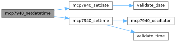
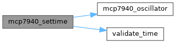
◆ mcp7940_settime()
| MCP7940_Error mcp7940_settime | ( | const FORMAT_Time * | time | ) |
Sets the current time of the MCP7940 RTC from a FORMAT_Time structure.
- Parameters
-
time Pointer to a FORMAT_Time structure containing the time to be set. The following fields are used: time->hour(expected range: 0–23)time->minute(expected range: 0–59)time->second(expected range: 0–59)
- Returns
- Returns one of the following error codes:
- MCP7940_Error_None if the supplied time is valid and the MCP7940 registers were updated successfully.
- MCP7940_Error_Fail if the supplied time is invalid according to validate_time() and no write is attempted.
This function first validates the time fields using validate_time(). If validation fails, it returns MCP7940_Error_Fail immediately. Otherwise, it writes the hour, minute, and second values to the MCP7940 RTCHOUR, RTCMIN, and RTCSEC registers using mcp7940_setdata(), then enables the RTC oscillator via mcp7940_oscillator() so that timekeeping starts or continues from the new value. The implementation assumes that conversion to the device’s register format (for example BCD) is handled inside mcp7940_setdata().

◆ mcp7940_setweekday()
| MCP7940_Error mcp7940_setweekday | ( | unsigned char | weekday | ) |
Sets the MCP7940 weekday field in the RTCWKDAY register.
- Parameters
-
weekday Zero-based weekday index to be written to the device. Valid values are: - 0 for the first day of the week (mapped to device value 1),
- 1 for the second day of the week (mapped to device value 2),
- ...
- 6 for the seventh day of the week (mapped to device value 7).
Values greater than or equal to 7 are rejected.
- Returns
- Returns one of the following error codes:
- MCP7940_Error_None if
weekdayis within range and the RTCWKDAY register was updated. - MCP7940_Error_Fail if
weekdayis out of range (>= 7) and the register is not modified.
- MCP7940_Error_None if
This function programs the weekday field of the MCP7940 RTCWKDAY register. The MCP7940 encodes weekday values in the range 1–7, so the provided zero-based weekday is incremented by 1 and masked with 0x07 before being written. The existing upper bits of RTCWKDAY (such as VBATEN, PWRFAIL, and OSCRUN) are preserved by masking with 0xF8 and OR-ing in the new weekday value.
◆ mcp7940_status()
| MCP7940_Status mcp7940_status | ( | void | ) |
Reads and returns the current MCP7940 status flags from the weekday register.
- Returns
- A MCP7940_Status value containing a bitwise combination of:
- MCP7940_Status_Oscillator_Running if the OSCRUN bit is set, indicating that the oscillator is currently running.
- MCP7940_Status_Power_Fail if the PWRFAIL bit is set, indicating that a power-fail event has been logged and the corresponding time stamps are available.
- MCP7940_Status_Battery_Enabled if the VBATEN bit is set, indicating that battery backup mode is enabled.
If none of these bits are set, the function returns MCP7940_Status_None.
This function reads the RTCWKDAY register of the MCP7940 and masks out the OSCRUN, PWRFAIL, and VBATEN bits to construct an MCP7940_Status value. The resulting status can be used by higher-level code to determine whether the RTC oscillator is running, whether a power failure has occurred, and whether battery backup is configured.
< Bit mask for the OSCRUN flag indicating that the oscillator is running.
< Bit mask for the PWRFAIL flag indicating that a power failure has occurred.
< Bit mask for the VBATEN flag enabling battery-backed timekeeping.
◆ mcp7940_time()
| void mcp7940_time | ( | FORMAT_Time * | time, |
| MCP7940_Register | reg ) |
Reads hour, minute, and second fields from the MCP7940 into a FORMAT_Time structure.
- Parameters
-
time Pointer to a FORMAT_Time structure that will be populated with time information from the MCP7940 registers. On return: time->hourcontains the decoded hour value.time->minutecontains the decoded minute value.time->secondcontains the decoded second value for current time, or 0 for power-up/power-down timestamp selections.
reg Selects which MCP7940 register set to read, using a value from MCP7940_Register: - MCP7940_Register_Current_Time to read the live time registers.
- MCP7940_Register_Power_Down_Time to read the power-down timestamp.
- MCP7940_Register_Power_Up_Time to read the power-up timestamp.
This function uses helper routines (mcp7940_hour(), mcp7940_minute(), and optionally mcp7940_second()) to extract the hour and minute from the selected MCP7940 time/timestamp registers and write them into time. For the current time selection, seconds are also read via mcp7940_second(). For power-down and power-up timestamp registers, the seconds field is not read and time->second is set to 0, since those registers do not store a separate seconds value in this implementation.

◆ mcp7940_trimming()
| MCP7940_Error mcp7940_trimming | ( | MCP7940_Trim | mode, |
| unsigned char | value ) |
Configures the MCP7940 oscillator trimming value and verifies the write.
- Parameters
-
mode Selects the trim direction, using a value from MCP7940_Trim: - MCP7940_Trim_Substract to subtract clock cycles (correct a fast clock).
- MCP7940_Trim_Add to add clock cycles (correct a slow clock).
value Raw trim magnitude to apply to the OSCTRIM register. Only the lower 7 bits (bit 6:0) are used as the trim value; bit 7 is set or cleared internally by this function according to modeto encode the sign of the adjustment. A value of 0 disables digital trimming.
- Returns
- Returns one of the following error codes:
- MCP7940_Error_None if the OSCTRIM register was written successfully and a subsequent readback matches the programmed value.
- MCP7940_Error_Fail if the readback of OSCTRIM does not match, indicating a possible I2C communication or device error.
This function masks value to seven bits, applies the sign bit according to the selected trim mode, and writes the resulting byte to the MCP7940 OSCTRIM register to adjust the RTC oscillator frequency. It then reads back the OSCTRIM register and compares it to the written value to confirm that the configuration was accepted by the device.
◆ mcp7940_weekday()
| unsigned char mcp7940_weekday | ( | MCP7940_Register | data | ) |
Reads the weekday value from the MCP7940 for the selected timestamp register set.
- Parameters
-
data Selects which MCP7940 register block to read the weekday from, using a value from MCP7940_Register: - MCP7940_Register_Current_Time to read the current weekday from RTCWKDAY.
- MCP7940_Register_Power_Down_Time to read the power-down weekday from PWRDNMTH.
- MCP7940_Register_Power_Up_Time to read the power-up weekday from PWRUPMTH.
- Returns
- An unsigned 3-bit weekday value in the range 0–7, where the underlying MCP7940 encoding uses 1–7 for the day-of-week and 0 may be returned if the register contents are not yet initialized.
This function extracts the weekday field from the appropriate MCP7940 register depending on data. For the power-down and power-up timestamp registers, the weekday bits are located in the upper three bits of the month register (PWRDNMTH or PWRUPMTH) and are right-shifted by MCP7940_PWRWEEKDAY_bp after masking. For the current time, the weekday is read directly from the RTCWKDAY register and masked with 0x07 to return only the weekday bits.
< Bit position of the least significant bit of the weekday field in the power-fail timestamp month registers.
< Bit position of the least significant bit of the weekday field in the power-fail timestamp month registers.
◆ mcp7940_weekday_string()
| const char * mcp7940_weekday_string | ( | unsigned char | day | ) |
Returns a three-letter weekday abbreviation for a given day value.
- Parameters
-
day Encoded weekday value in the MCP7940 format (1–7 expected), where: - 1 maps to "MON"
- 2 maps to "TUE"
- 3 maps to "WED"
- 4 maps to "THU"
- 5 maps to "FRI"
- 6 maps to "SAT"
- 7 maps to "SUN" Any other value is wrapped into this range and may yield the fallback "???".
- Returns
- Pointer to a constant, null-terminated string containing the three-letter weekday abbreviation corresponding to
day.
This function converts the MCP7940 weekday encoding into a human-readable three-character abbreviation by masking and normalizing the input value into the index range of the internal weeksdays lookup table. The returned pointer refers to a static string and remains valid for the lifetime of the program.