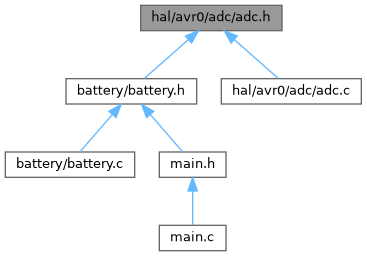
ADC (Analog-to-Digital Converter) configuration and control for AVR microcontrollers. More...
#include <avr/io.h>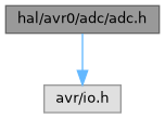
Go to the source code of this file.
Macros | |
| #define | ADC_RESOLUTION ADC_RESSEL_10BIT_gc |
| Defines the resolution of the ADC conversion. | |
| #define | ADC_CAPACITANCE 1 |
| Configures the ADC input capacitance setting for the AVR microcontroller. | |
| #define | ADC_REFERENCE ADC_REFSEL_INTREF_gc |
| Selects the reference voltage source for the ADC conversions. | |
| #define | VREF_REFSEL VREF_ADC0REFSEL_1V5_gc |
| Selects the internal reference voltage level for the ADC when using the internal reference. | |
| #define | ADC_PRESCALER ADC_PRESC_DIV256_gc |
| Sets the division factor for the ADC input clock derived from the system clock. | |
| #define | ADC_INIT_DELAY ADC_INITDLY_DLY0_gc |
| Defines the ADC clock delay before starting the conversion. | |
| #define | ADC_SAMPLE_DELAY_VARIATION ADC_ASDV_ASVOFF_gc |
| Enables or disables automatic sampling delay variation for the ADC. | |
| #define | ADC_SAMPLE_DELAY 8 |
| Configures the delay time between individual ADC sample acquisitions. | |
| #define | ADC_SAMPLE_LENGTH 8 |
| Specifies the sample length duration for ADC conversions. | |
Typedefs | |
| typedef enum ADC_Accumulation_t | ADC_Accumulation |
| Alias for enum ADC_Accumulation_t representing ADC sample accumulation modes. | |
| typedef enum ADC_Channel_t | ADC_Channel |
| Alias for enum ADC_Channel_t representing ADC input channel selections. | |
Enumerations | |
| enum | ADC_Accumulation_t { ADC_Sample_None =ADC_SAMPNUM_ACC1_gc , ADC_Sample_2 =ADC_SAMPNUM_ACC2_gc , ADC_Sample_4 =ADC_SAMPNUM_ACC4_gc , ADC_Sample_8 =ADC_SAMPNUM_ACC8_gc , ADC_Sample_16 =ADC_SAMPNUM_ACC16_gc , ADC_Sample_32 =ADC_SAMPNUM_ACC32_gc , ADC_Sample_64 =ADC_SAMPNUM_ACC64_gc } |
| Defines the number of ADC samples to be accumulated and averaged. More... | |
| enum | ADC_Channel_t { ADC_CH0 =ADC_MUXPOS_AIN0_gc , ADC_CH1 =ADC_MUXPOS_AIN1_gc , ADC_CH2 =ADC_MUXPOS_AIN2_gc , ADC_CH3 =ADC_MUXPOS_AIN3_gc , ADC_CH4 =ADC_MUXPOS_AIN4_gc , ADC_CH5 =ADC_MUXPOS_AIN5_gc , ADC_CH6 =ADC_MUXPOS_AIN6_gc , ADC_CH7 =ADC_MUXPOS_AIN7_gc , ADC_CH8 =ADC_MUXPOS_AIN8_gc , ADC_CH9 =ADC_MUXPOS_AIN9_gc , ADC_CH10 =ADC_MUXPOS_AIN10_gc , ADC_CH11 =ADC_MUXPOS_AIN11_gc , ADC_INTREF =ADC_MUXPOS_INTREF_gc , ADC_GND =ADC_MUXPOS_GND_gc } |
| Selects the ADC input channel. More... | |
Functions | |
| void | adc_init (void) |
| Initialize the ADC peripheral with pre-configured settings. | |
| void | adc_channel (ADC_Channel channel) |
| Select the ADC input channel. | |
| void | adc_accumulation (ADC_Accumulation samples) |
| Set the ADC sample accumulation mode. | |
| void | adc_disable (void) |
| Disable the ADC module. | |
| unsigned int | adc_read (void) |
| Perform a single ADC conversion and return the result (polling mode). | |
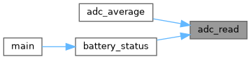
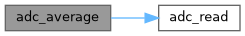
| unsigned int | adc_average (unsigned char samples) |
| Perform multiple ADC conversions and return the average result (calculated in software). | |
Detailed Description
ADC (Analog-to-Digital Converter) configuration and control for AVR microcontrollers.
This header file defines macros, enums, and function prototypes to configure and control the ADC peripheral of AVR microcontrollers. It allows the setup of ADC resolution, reference voltage, prescaler, sample accumulation, and channel selection. The ADC supports customizable parameters including sample delay, sample length, and reference voltage selection. Interrupt handling is not included in this library and should be implemented separately if needed.
- Date
- 2025-09-18
- Version
- 1.0 Release
- Copyright
- Copyright (c) 2025 g.raf Released under the GPLv3 License. (see LICENSE in repository)
- Note
- This file is part of a larger embedded systems project and subject to the license specified in the repository. For updates and the complete revision history, see the GitHub repository.
- See also
- https://github.com/0x007e/avr0 "AVR GitHub Repository"
Macro Definition Documentation
◆ ADC_CAPACITANCE
| #define ADC_CAPACITANCE 1 |
Configures the ADC input capacitance setting for the AVR microcontroller.
This macro selects the recommended capacitor setting connected to the ADC input reference pin based on the reference voltage level used. The options are:
- 0: Recommended for reference voltages below 1V
- 1: Recommended for higher reference voltages (default)
Proper capacitance selection can improve ADC stability and accuracy by stabilizing the reference voltage.
- Note
- Ensure that the physical capacitor used on the ADC reference pin matches this setting for optimal performance.
◆ ADC_INIT_DELAY
| #define ADC_INIT_DELAY ADC_INITDLY_DLY0_gc |
Defines the ADC clock delay before starting the conversion.
This macro sets the number of ADC clock cycles to wait after enabling the ADC and before starting a conversion. The delay allows the ADC internal circuitry to stabilize, improving conversion accuracy. Possible values with corresponding clock cycles include:
- ADC_INITDLY_DLY0_gc : 0 cycles (no delay)
- ADC_INITDLY_DLY16_gc : 16 cycles
- ADC_INITDLY_DLY32_gc : 32 cycles
- ADC_INITDLY_DLY64_gc : 64 cycles
- ADC_INITDLY_DLY128_gc : 128 cycles
- ADC_INITDLY_DLY256_gc : 256 cycles
The default value is ADC_INITDLY_DLY0_gc (no delay).
- Note
- Proper delay selection may depend on the ADC configuration and the application requirements. Too small a delay may cause inaccurate conversions.
◆ ADC_PRESCALER
| #define ADC_PRESCALER ADC_PRESC_DIV256_gc |
Sets the division factor for the ADC input clock derived from the system clock.
This macro defines the prescaler setting that divides the system clock (F_PER) to generate the ADC clock frequency. The ADC requires an input clock frequency typically between 50 kHz and 1.5 MHz for accurate conversions, especially when using 10-bit resolution.
Valid prescaler options and their division factors include:
- ADC_PRESC_DIV2_gc : F_PER / 2
- ADC_PRESC_DIV4_gc : F_PER / 4
- ADC_PRESC_DIV8_gc : F_PER / 8
- ADC_PRESC_DIV16_gc : F_PER / 16
- ADC_PRESC_DIV32_gc : F_PER / 32
- ADC_PRESC_DIV64_gc : F_PER / 64
- ADC_PRESC_DIV128_gc : F_PER / 128
- ADC_PRESC_DIV256_gc : F_PER / 256 (default)
Choosing the appropriate prescaler ensures the ADC clock frequency lies within the recommended range, balancing conversion speed and accuracy.
- Note
- Incorrect prescaler settings may lead to inaccurate ADC readings or failure to meet timing requirements.
◆ ADC_REFERENCE
| #define ADC_REFERENCE ADC_REFSEL_INTREF_gc |
Selects the reference voltage source for the ADC conversions.
This macro defines the reference voltage used by the ADC for analog-to-digital conversions. Options typically include:
- ADC_REFSEL_INTREF_gc: Internal reference voltage (default)
- ADC_REFSEL_VDDREF_gc: VDD (power supply) as reference voltage
The chosen reference voltage affects the conversion range and accuracy. The internal reference provides a stable known voltage, whereas VDD varies with supply voltage.
- Note
- Ensure the selected reference voltage corresponds to the hardware setup for correct ADC readings.
◆ ADC_RESOLUTION
| #define ADC_RESOLUTION ADC_RESSEL_10BIT_gc |
Defines the resolution of the ADC conversion.
This macro selects the ADC resolution mode for the AVR microcontroller's ADC. The available options are:
- ADC_RESSEL_10BIT_gc for 10-bit resolution (default)
- ADC_RESSEL_8BIT_gc for 8-bit resolution
The resolution affects the precision and size of the ADC conversion result. A higher resolution provides finer granularity but may require longer conversion times.
- Note
- Choose the resolution based on the application's precision requirements and system constraints.
◆ ADC_SAMPLE_DELAY
| #define ADC_SAMPLE_DELAY 8 |
Configures the delay time between individual ADC sample acquisitions.
This macro defines the number of clock cycles to wait between samples during ADC conversion. Valid values range from 0 to 15 clock cycles. The default value is set to 8 cycles. Adjusting this delay allows tuning of the ADC sampling frequency and can help reduce noise or interference effects.
- Note
- The optimal delay depends on the specific ADC hardware and application requirements.
◆ ADC_SAMPLE_DELAY_VARIATION
| #define ADC_SAMPLE_DELAY_VARIATION ADC_ASDV_ASVOFF_gc |
Enables or disables automatic sampling delay variation for the ADC.
This macro configures whether the ADC hardware automatically varies the delay between sample acquisitions. Options include:
- ADC_ASDV_ASVOFF_gc : Automatic sampling delay variation disabled (default)
- ADC_ASDV_ASVON_gc : Automatic sampling delay variation enabled
Enabling this feature randomizes the sampling delay slightly between consecutive ADC conversions, which can help reduce noise and interference effects such as harmonic disturbances in the analog signal.
- Note
- This feature is especially useful in applications where periodic noise patterns interfere with accurate ADC readings. Disabling it uses a fixed sample delay.
◆ ADC_SAMPLE_LENGTH
| #define ADC_SAMPLE_LENGTH 8 |
Specifies the sample length duration for ADC conversions.
This macro defines the amount of time, in ADC clock cycles, that the ADC samples the input signal before starting the conversion. Valid values range from 0 to 31 cycles. The default value is set to 8 cycles. Longer sample lengths can improve measurement stability and accuracy, especially when measuring high-impedance sources.
- Note
- Adjust this setting based on the source impedance and noise characteristics of the signal.
◆ VREF_REFSEL
| #define VREF_REFSEL VREF_ADC0REFSEL_1V5_gc |
Selects the internal reference voltage level for the ADC when using the internal reference.
This macro defines the exact internal voltage reference selected for the ADC when the ADC_REFERENCE macro is set to ADC_REFSEL_INTREF_gc (internal reference). Possible options include:
- VREF_ADC0REFSEL_0V55_gc : 0.55 V internal reference
- VREF_ADC0REFSEL_1V1_gc : 1.1 V internal reference
- VREF_ADC0REFSEL_1V5_gc : 1.5 V internal reference (default)
- VREF_ADC0REFSEL_2V5_gc : 2.5 V internal reference
Proper selection of the internal reference voltage is critical for accurate ADC conversions and must match the hardware configuration and application requirements.
- Note
- This macro is only defined and used if ADC_REFERENCE is set to the internal reference.
Typedef Documentation
◆ ADC_Accumulation
| typedef enum ADC_Accumulation_t ADC_Accumulation |
Alias for enum ADC_Accumulation_t representing ADC sample accumulation modes.
◆ ADC_Channel
| typedef enum ADC_Channel_t ADC_Channel |
Alias for enum ADC_Channel_t representing ADC input channel selections.
Enumeration Type Documentation
◆ ADC_Accumulation_t
| enum ADC_Accumulation_t |
Defines the number of ADC samples to be accumulated and averaged.
This enumeration provides options for accumulating multiple ADC samples into a single averaged result. Accumulation helps reduce noise and increase measurement accuracy by averaging multiple samples.
Values correspond to the number of samples used in accumulation:
- ADC_Sample_None (1 sample)
- ADC_Sample_2 (2 samples)
- ADC_Sample_4 (4 samples)
- ADC_Sample_8 (8 samples)
- ADC_Sample_16 (16 samples)
- ADC_Sample_32 (32 samples)
- ADC_Sample_64 (64 samples)
| Enumerator | |
|---|---|
| ADC_Sample_None | |
| ADC_Sample_2 | |
| ADC_Sample_4 | |
| ADC_Sample_8 | |
| ADC_Sample_16 | |
| ADC_Sample_32 | |
| ADC_Sample_64 | |
◆ ADC_Channel_t
| enum ADC_Channel_t |
Selects the ADC input channel.
This enumeration represents the available analog input channels for the ADC on the AVR microcontroller. It includes external analog input pins, internal reference voltages, and ground.
Channels include:
- ADC_CH0 to ADC_CH11 : External ADC input pins AIN0 to AIN11
- ADC_INTREF : Internal reference voltage input
- ADC_GND : Ground reference input
| Enumerator | |
|---|---|
| ADC_CH0 | |
| ADC_CH1 | |
| ADC_CH2 | |
| ADC_CH3 | |
| ADC_CH4 | |
| ADC_CH5 | |
| ADC_CH6 | |
| ADC_CH7 | |
| ADC_CH8 | |
| ADC_CH9 | |
| ADC_CH10 | |
| ADC_CH11 | |
| ADC_INTREF | |
| ADC_GND | |
Function Documentation
◆ adc_accumulation()
| void adc_accumulation | ( | ADC_Accumulation | samples | ) |
Set the ADC sample accumulation mode.
- Parameters
-
samples The ADC_Accumulation enum value specifying how many ADC samples to accumulate and average.
This function configures the ADC to accumulate multiple samples before producing a conversion result, which helps reduce noise and improve measurement accuracy. The accumulation count is set by writing to the ADC control register B.
- Note
- The ADC must be configured and enabled for the accumulation mode to take effect.
◆ adc_average()
| unsigned int adc_average | ( | unsigned char | samples | ) |
Perform multiple ADC conversions and return the average result (calculated in software).
- Parameters
-
samples Number of ADC samples to average.
This function reads the ADC conversion result multiple times by calling adc_read(), sums the results, and calculates the average value to reduce noise and improve stability. It returns the averaged ADC value as an unsigned int.
- Note
- This method provides a simple software averaging filter for ADC measurements.
- Returns
- The averaged ADC conversion result.
◆ adc_channel()
|
inline |
Select the ADC input channel.
- Parameters
-
channel ADC channel to select from the ADC_Channel enumeration.
This inline function sets the ADC multiplexer positive input selection register to the specified channel, masking and shifting the channel value appropriately. The channel selects which analog input pin or internal reference the ADC samples.
- Note
- Ensure the channel value is valid and corresponds to a supported ADC input.

◆ adc_disable()
|
inline |
Disable the ADC module.
This inline function disables the ADC by clearing the enable bit in the ADC control register. Disabling the ADC conserves power when ADC functionality is not required.
- Note
- It is recommended to disable the ADC before entering low-power modes to minimize current consumption.

◆ adc_init()
| void adc_init | ( | void | ) |
Initialize the ADC peripheral with pre-configured settings.
Configures the ADC control registers for capacitance, reference voltage, prescaler, sample delay variation, initial delay, and sample length according to compile-time macros. Enables the ADC with the selected resolution. If the ADC interrupt mode is enabled, the ADC result ready interrupt is also enabled. When using the internal voltage reference, the voltage reference control register is configured accordingly. This function must be called before starting any ADC conversions to ensure proper setup.
- Note
- Interrupt vectors and ADC interrupt handling routines must be implemented separately when enabling interrupts.
◆ adc_read()
| unsigned int adc_read | ( | void | ) |
Perform a single ADC conversion and return the result (polling mode).
Starts an ADC conversion by setting the START command bit in the ADC command register. The function then polls the command register until the conversion completes by checking the START bit. After completion, it returns the 16-bit (10-bit ADC result) value from the ADC result register.
- Note
- This function blocks execution until the conversion is finished.
- Returns
- The ADC conversion result as an unsigned int.