LED control interface for AVR microcontrollers using SPI. More...
Go to the source code of this file.
Data Structures | |
| struct | LED_Data_t |
| Represents the data structure for a single LED including color and intensity. More... | |
Macros | |
| #define | F_CPU 20000000UL |
| System clock frequency definition. | |
| #define | LED_NUMBER_OF_LEDS 2 |
| Defines the total number of LEDs controlled by the driver. | |
| #define | LED_FRAME_SIZE 4 |
| Defines the size of the LED start/stop data frame in bytes. | |
| #define | LED_START_VALUE 0x00 |
| Defines the start-of-frame marker value for LED data transmission. | |
| #define | LED_STOP_VALUE 0xFF |
| Defines the end-of-frame marker value for LED data transmission. | |
| #define | LED_ENABLE_FLAG 0xE0 |
| Flag used to enable LED operation. | |
| #define | LED_SLEEP_FLAG 0xA0 |
| Flag used to set the LED device into sleep mode. | |
| #define | LED_MIN_INTENSITY 0x01 |
| The minimum intensity value for LED brightness. | |
| #define | LED_MAX_INTENSITY 0x0F |
| The maximum intensity value for LED brightness. | |
| #define | LED_SOF() |
| Sends the Start-of-Frame (SOF) signal to the LED strip. | |
| #define | LED_EOF() |
| Sends the End-of-Frame (EOF) signal to the LED strip. | |
Typedefs | |
| typedef enum LED_Status_t | LED_Status |
| Alias for enum LED_Status_t representing possible LED system status codes. | |
| typedef enum LED_Delay_t | LED_Delay |
| Alias for enum LED_Delay_t representing predefined LED blink delay durations. | |
| typedef enum LED_Position_t | LED_Position |
| Alias for enum LED_Position_t representing LED position flags and blinking options. | |
| typedef struct LED_Data_t | LED_Data |
| Alias for struct LED_Data_t representing LED color and intensity data. | |
Enumerations | |
| enum | LED_Status_t { LED_Status_None =0 , LED_Status_Ready , LED_Status_Warning , LED_Status_Error } |
| Enumerates possible LED status types indicating different system states. More... | |
| enum | LED_Delay_t { LED_Delay_None =0 , LED_Delay_MS_100 , LED_Delay_MS_200 , LED_Delay_MS_300 , LED_Delay_MS_400 , LED_Delay_MS_500 } |
| Defines selectable delay durations for LED blinking actions. More... | |
| enum | LED_Position_t { LED_Position_None =0x00 , LED_Position_Left =0x01 , LED_Position_Right =0x02 , LED_Position_Left_Alternating =0x04 , LED_Position_Right_Alternating =0x08 } |
| Defines LED position flags and alternating blinking modes. More... | |
Functions | |
| void | led_init (void) |
| Initialize the LED control interface and hardware. | |
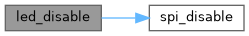
| void | led_disable (void) |
| Disable the LED hardware interface. | |
| void | led_xof (unsigned char value) |
| Transmit a specified value repeatedly over SPI to form a data frame. | |
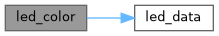
| void | led_data (LED_Data data) |
| Send an LED data frame with specified color and intensity. | |
| void | leds_off (void) |
| Turn off all LEDs by sending zero-intensity frames. | |
| LED_Data | led_status_color (LED_Status status, unsigned char intensity) |
| Generate a color configuration for an LED based on its status and intensity. | |
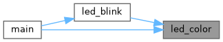
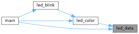
| void | led_color (LED_Position position, LED_Data color) |
| Set the colors of specified LEDs based on position flags. | |
| void | led_blink (LED_Position position, LED_Data color, LED_Delay delay, unsigned char repeat) |
| Blink LEDs on specified positions with given color, delay and repeat count. | |
Detailed Description
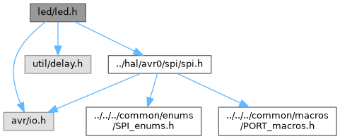
LED control interface for AVR microcontrollers using SPI.
This header file defines the interface for controlling LEDs, including configuration macros, status and delay enumerations, LED position flags, and data structures for LED color and intensity. Functions are provided to initialize LED hardware, send data frames via SPI, control LED colors, and perform LED blinking actions. The LED driver supports multiple LEDs with configurable frame sizes and intensity limits.
- Date
- 2025-09-28
- Version
- 1.0 Release
- Copyright
- Copyright (c) 2025 g.raf Released under the GPLv3 License. (see LICENSE in repository)
- Note
- This file is part of a larger embedded systems project and subject to the license specified in the repository. For updates and the complete revision history, see the GitHub repository.
- See also
- https://github.com/0x007e/rcc "AVR ATmega GitHub Repository"
Macro Definition Documentation
◆ F_CPU
| #define F_CPU 20000000UL |
System clock frequency definition.
This macro defines the operating frequency of the microcontroller's clock in Hertz. It is used by delay functions and timing calculations. The value should match the actual hardware clock frequency to ensure correct timing behavior in the software.
◆ LED_ENABLE_FLAG
| #define LED_ENABLE_FLAG 0xE0 |
Flag used to enable LED operation.
This flag value, default 0xE0, is used in communication settings to signal enabling the LED device or functionality.
◆ LED_EOF
| #define LED_EOF | ( | ) |
Sends the End-of-Frame (EOF) signal to the LED strip.
This macro transmits the predefined LED_STOP_VALUE as an end frame delimiter using the function led_xof(). It inserts a short delay of 10 microseconds to ensure proper timing after LED data transmission ends. The EOF indicates the completion of the current LED data sequence.
◆ LED_FRAME_SIZE
| #define LED_FRAME_SIZE 4 |
Defines the size of the LED start/stop data frame in bytes.
This macro indicates how many bytes make up a start/stop LED data frame sent via SPI. The default frame size is 4 bytes.
- Note
- Modify this value if the LED hardware protocol requires a different start/stop frame size.
◆ LED_MAX_INTENSITY
| #define LED_MAX_INTENSITY 0x0F |
The maximum intensity value for LED brightness.
This macro defines the highest valid intensity level for LED brightness. The default maximum is 0x0F.
◆ LED_MIN_INTENSITY
| #define LED_MIN_INTENSITY 0x01 |
The minimum intensity value for LED brightness.
This macro defines the lowest valid intensity level for LED brightness. The default minimum is 0x01.
◆ LED_NUMBER_OF_LEDS
| #define LED_NUMBER_OF_LEDS 2 |
Defines the total number of LEDs controlled by the driver.
This macro specifies how many individual LEDs are connected and managed. The default is 2 LEDs.
- Note
- Override as needed for the actual number of LEDs in the hardware configuration.
◆ LED_SLEEP_FLAG
| #define LED_SLEEP_FLAG 0xA0 |
Flag used to set the LED device into sleep mode.
The value 0xA0 is used to command the LED device to enter a low power or sleep state.
◆ LED_SOF
| #define LED_SOF | ( | ) |
Sends the Start-of-Frame (SOF) signal to the LED strip.
This macro transmits the predefined LED_START_VALUE as a start frame delimiter using the function led_xof(). It inserts a short delay of 10 microseconds to ensure proper timing before subsequent LED data transmission begins. The SOF marks the beginning of a new LED data sequence.
◆ LED_START_VALUE
| #define LED_START_VALUE 0x00 |
Defines the start-of-frame marker value for LED data transmission.
This value is sent to indicate the start of a LED data frame sequence. The default start value is 0x00.
◆ LED_STOP_VALUE
| #define LED_STOP_VALUE 0xFF |
Defines the end-of-frame marker value for LED data transmission.
This value is sent to mark the end of a LED data frame sequence. The default stop value is 0xFF.
Typedef Documentation
◆ LED_Data
| typedef struct LED_Data_t LED_Data |
Alias for struct LED_Data_t representing LED color and intensity data.
◆ LED_Delay
| typedef enum LED_Delay_t LED_Delay |
Alias for enum LED_Delay_t representing predefined LED blink delay durations.
◆ LED_Position
| typedef enum LED_Position_t LED_Position |
Alias for enum LED_Position_t representing LED position flags and blinking options.
◆ LED_Status
| typedef enum LED_Status_t LED_Status |
Alias for enum LED_Status_t representing possible LED system status codes.
Enumeration Type Documentation
◆ LED_Delay_t
| enum LED_Delay_t |
Defines selectable delay durations for LED blinking actions.
This enumeration provides predefined delay durations to control the timing of LED blink cycles, ranging from no delay to 500 ms delay intervals.
| Enumerator | |
|---|---|
| LED_Delay_None | |
| LED_Delay_MS_100 | |
| LED_Delay_MS_200 | |
| LED_Delay_MS_300 | |
| LED_Delay_MS_400 | |
| LED_Delay_MS_500 | |
◆ LED_Position_t
| enum LED_Position_t |
Defines LED position flags and alternating blinking modes.
This enumeration specifies individual LED positions and options for alternating blinking patterns. Positions include left and right LEDs, as well as flags for alternating blink sequences.
| Enumerator | |
|---|---|
| LED_Position_None | |
| LED_Position_Left | |
| LED_Position_Right | |
| LED_Position_Left_Alternating | |
| LED_Position_Right_Alternating | |
◆ LED_Status_t
| enum LED_Status_t |
Enumerates possible LED status types indicating different system states.
This enumeration defines the LED status codes used to represent system conditions via LED color or behavior. It includes states such as Ready, Warning, and Error.
| Enumerator | |
|---|---|
| LED_Status_None | |
| LED_Status_Ready | |
| LED_Status_Warning | |
| LED_Status_Error | |
Function Documentation
◆ led_blink()
| void led_blink | ( | LED_Position | position, |
| LED_Data | color, | ||
| LED_Delay | delay, | ||
| unsigned char | repeat ) |
Blink LEDs on specified positions with given color, delay and repeat count.
- Parameters
-
position Bitwise flags indicating LED positions and blinking modes to be used. color The color and intensity to blink on the LEDs. delay Enumeration specifying delay duration between blink states. repeat The number of times to repeat the blink sequence.
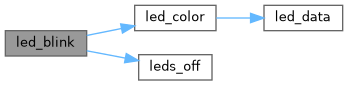
This function controls blinking patterns for LEDs by alternately activating the specified LED positions and their alternating blinking counterparts. It uses the function led_color to set the color, and led_delay to wait between blinking states. The blinking sequence runs for repeat cycles, then turns off all LEDs using leds_off().
- Note
- Ensure the SPI interface and LED hardware are properly initialized before calling this function. The delay parameter controls brightness on/off period in milliseconds.
- See also
- led_color() for setting LED colors.
- led_delay() for insertion of delay intervals.
- leds_off() to turn off LEDs after blinking completes.

◆ led_color()
| void led_color | ( | LED_Position | position, |
| LED_Data | color ) |
Set the colors of specified LEDs based on position flags.
- Parameters
-
position Bitwise flags indicating which LEDs to color and their blinking modes. color The LED_Data structure specifying color and intensity for the LEDs.
This function initiates an LED data frame sequence by sending a start-of-frame (SOF) signal. It then iterates over all configured LEDs and determines, based on their position and the position flags, whether to set the LED color to the specified color or turn the LED off.
For odd numbers of LEDs, the middle LED is always turned off. The function supports left and right LED positions as well as alternating blinking flags. The LED data or off frames are sent accordingly. Finally, an end-of-frame (EOF) signal is sent to mark the completion of the LED update.
- Note
- Ensure the SPI interface is initialized and the LED hardware supports the specified frame format.
- See also
- LED_SOF(), LED_EOF() for frame delimiters.
- led_data() and led_off() for sending LED on/off frames.
◆ led_data()
| void led_data | ( | LED_Data | data | ) |
Send an LED data frame with specified color and intensity.
- Parameters
-
data LED_Data structure containing intensity and RGB color values.
This function constructs and transmits a single LED data frame over SPI, combining the LED enable flag with the masked intensity value, followed by the blue, green, and red color components. The intensity value is masked with 0x3F to limit it to valid bits.
The frame format is:
- Mode byte: LED_ENABLE_FLAG OR'ed with intensity (0x3F mask).
- Blue color byte.
- Green color byte.
- Red color byte.
- Note
- Ensure the LED is initialized before calling this function.
◆ led_disable()
| void led_disable | ( | void | ) |
Disable the LED hardware interface.
This function sends multiple sleep commands to all configured LEDs to put them into a low power state. It transmits four repeated LED sleep frames using SPI and then disables the SPI peripheral itself.
This operation is used to safely turn off the LEDs and reduce power consumption when LED functionality is not needed.
- Note
- Ensure no ongoing LED data transmission occurs before calling this function to avoid communication issues.
- See also
- spi_disable() for disabling the SPI communication peripheral.
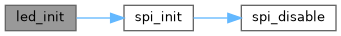
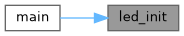
◆ led_init()
| void led_init | ( | void | ) |
Initialize the LED control interface and hardware.
This function initializes the SPI peripheral to communicate with the LEDs using most significant bit (MSB) first, with clock polarity and phase set to rising edges. After SPI initialization, it sends a start-of-frame (SOF) signal followed by initializing all configured LEDs with the enable flag and zero color data (LEDs initially off). Finally, it sends an end-of-frame (EOF) signal to mark completion of the initialization sequence. This setup prepares the LEDs for subsequent color and blink control operations by configuring the communication and initial states.
- Note
- This function must be called before any other LED control operations. It assumes SPI_MSB, SPI_Rising macros and LED frame configurations are correctly defined.
- See also
- spi_init() for SPI communication setup.
- LED_SOF() and LED_EOF() macros for frame delimiters.
- led_frame() for sending individual LED data frames.
◆ led_status_color()
| LED_Data led_status_color | ( | LED_Status | status, |
| unsigned char | intensity ) |
Generate a color configuration for an LED based on its status and intensity.
- Parameters
-
status The LED status indicating the system state (e.g., ready, warning, error). intensity The brightness intensity level for the LED (0-255).
- Returns
- Returns an LED_Data structure populated with the RGB color values corresponding to the specified status and intensity.
This function initializes an LED_Data structure with the provided intensity and default black color (all zero). It then assigns color values based on the status:
- LED_Status_Ready assigns full green brightness,
- LED_Status_Warning assigns full red and green brightness (yellow),
- LED_Status_Error assigns full red brightness.
This mapping follows common LED indicator color conventions to visually represent different states.
- Note
- The returned color values are maximum brightness (0x3F) for the color channels, regardless of the input intensity which only affects overall brightness.

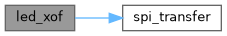
◆ led_xof()
| void led_xof | ( | unsigned char | value | ) |
Transmit a specified value repeatedly over SPI to form a data frame.
- Parameters
-
value The byte value to be sent repeatedly.
This function sends the given value repeatedly for LED_FRAME_SIZE times via SPI using the spi_transfer function. It is commonly used to send start or stop frames for LED data sequences to synchronize communication with the LED hardware.
- Note
- The function blocks until all bytes are transmitted. Ensure the SPI interface is initialized before calling this function.
◆ leds_off()
| void leds_off | ( | void | ) |
Turn off all LEDs by sending zero-intensity frames.
This function sends a start-of-frame signal followed by zero-intensity data frames to all configured LEDs, effectively turning them off. It concludes by sending an end-of-frame signal. This ensures all LEDs are turned off cleanly by resetting their color and intensity data.
- Note
- This function assumes the SPI interface is already initialized and ready for communication. Use led_off() internally to send individual LED off frames.