Source file with implementation of hardware SPI functions and macros. More...
#include "spi.h"
Functions | |
| SPI_Status | spi_init (SPI_Direction direction, SPI_Polarity setup, SPI_Phase sample) |
| Initialize the SPI hardware interface in master mode with specified configuration. | |
| void | spi_disable (void) |
| Disable the SPI hardware interface and reset related pins. | |
| void | spi_select (SPI_Select mode) |
| Control the SPI Slave Select (SS) pin to enable or disable the SPI slave device. | |
| unsigned char | spi_transfer (unsigned char data) |
| Transfer a single byte of data over the SPI bus. | |
Detailed Description
Source file with implementation of hardware SPI functions and macros.
This file contains the definitions of function implementations and macros for hardware-based SPI communication on AVR-0/1/2-Series microcontrollers.
- Date
- 2025-09-27
- Version
- 1.0 Release
- Copyright
- Copyright (c) 2025 g.raf Released under the GPLv3 License. (see LICENSE in repository)
- Note
- This file is part of a larger project and subject to the license specified in the repository. For updates and the complete revision history, see the GitHub repository.
- Important
- The SS pin must be HIGH during initialization of the bus to avoid unintended slave mode configuration.
- See also
- spi.h for declarations and related information.
- https://github.com/0x007e/avr0 "AVR ATmega GitHub Repository"
Function Documentation
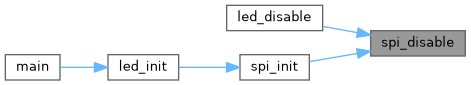
◆ spi_disable()
| void spi_disable | ( | void | ) |
Disable the SPI hardware interface and reset related pins.
This function disables the SPI peripheral on the AVR ATTiny series device by clearing the master and enable bits in the SPI control register. It also resets the SPI mode bits to their default state. The function configures the SPI-related pins (MOSI, MISO, SCK, SS) by clearing their direction bits, effectively disabling SPI pin control, and drives these pins low by clearing the output register. Additionally, the pull-up resistor on the SS pin is disabled. If SPI interrupts are enabled via the SPI_SPIE macro, this function disables SPI interrupt requests. The port multiplexer configuration for SPI is cleared and the SPI interrupt flags are reset.
- Note
- After calling this function, the SPI peripheral and associated pins are fully disabled, which is necessary before changing SPI configurations or powering down the SPI module to reduce power consumption.
◆ spi_init()
| SPI_Status spi_init | ( | SPI_Direction | direction, |
| SPI_Polarity | setup, | ||
| SPI_Phase | sample ) |
Initialize the SPI hardware interface in master mode with specified configuration.
- Parameters
-
direction Specifies the bit order for SPI data transmission (MSB or LSB first). setup Specifies the clock polarity (SPI_Polarity) to configure the clock idle state. sample Specifies the clock phase (SPI_Phase) to configure the clock sampling edge.
- Returns
- Returns an SPI_Status code indicating the result of initialization. Possible return values:
- SPI_None: Initialization completed successfully.
- SPI_Master_Abort: Initialization was aborted due to the Slave Select (SS) pin being low when SPI_ENABLE_MASTER_ABORT is enabled.
This function configures the SPI peripheral registers on the AVR ATTiny series device to initialize the SPI bus in master mode. It sets the SPI port multiplexer, configures the data direction for SPI pins, and sets up the SPI clock phase and polarity according to the specified parameters.
- Important
- If the macro SPI_ENABLE_MASTER_ABORT is defined, special handling is enabled: if during initialization the SS pin is detected low, the SPI master initialization is aborted by disabling the SPI peripheral and returning the status SPI_Master_Abort.
The function also sets pull-up resistors on the MISO and SS pins according to configuration, and configures SPI interrupts if the SPI_SPIE macro is defined.
- Note
- Ensure that the SPI pins and port multiplexer settings correspond to your hardware configuration. The function assumes a default SPI clock prescaler; customize SPI_CLOCK and SPI2X_ENABLE macros for different clock rates.
- See also
- SPI_Direction, SPI_Polarity, SPI_Phase for parameter options and configuration.
- spi_disable() for disabling the SPI peripheral in case of master abort.


◆ spi_select()
| void spi_select | ( | SPI_Select | mode | ) |
Control the SPI Slave Select (SS) pin to enable or disable the SPI slave device.
- Parameters
-
mode Specifies the SPI select state, either SPI_Enable or SPI_Disable.
This function manages the SPI Slave Select (SS) pin using the configured SPI port. When SPI_Enable is passed, the SS pin is driven low to select (activate) the SPI slave device. For any other value, the SS pin is driven high, deselecting (deactivating) the slave. This control is essential for ensuring that only one SPI slave device communicates with the master at any given time on a shared SPI bus.
- Note
- The SS pin behavior is active low; pulling it low selects the slave. Ensure that the pin configuration and port macros reflect your hardware's SPI setup.
◆ spi_transfer()
| unsigned char spi_transfer | ( | unsigned char | data | ) |
Transfer a single byte of data over the SPI bus.
- Parameters
-
data The byte value to be sent via SPI.
- Returns
- Returns the byte received simultaneously from the SPI slave device.
This function writes the provided data byte to the SPI data register, initiating the SPI transmission. It then waits in a busy loop until the SPI interrupt flag indicates that the transfer is complete. Upon completion, the function reads and returns the received byte from the SPI data register. SPI communication is full-duplex, so while sending a byte, a byte is received simultaneously. This function therefore effectively performs a combined send/receive operation.
- Note
- This is a blocking call that waits until the SPI hardware signals transmission completion. Ensure SPI is properly initialized before calling this function.