Header file with declarations and macros for hardware SPI. More...
#include <avr/io.h>#include "../../../common/enums/SPI_enums.h"#include "../../../common/macros/PORT_macros.h"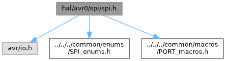
Go to the source code of this file.
Macros | |
| #define | SPI2X_ENABLE |
| Enables the SPI double speed mode. | |
| #define | SPI_CLOCK SPI_PRESC_DIV4_gc |
| Default SPI clock prescaler setting. | |
| #define | SPI_PORTMUX PORTMUX_SPI0_DEFAULT_gc |
| Selects the alternate port location for SPI pins. | |
| #define | SPI_PORTMUX PORTMUX_SPI0_DEFAULT_gc |
| Selects the alternate port location for SPI pins. | |
| #define | SPI_PORT PORTA |
| Specifies the port register for the SPI interface. | |
| #define | SPI_MOSI PIN1_bm |
| Specifies the bit mask for the SPI MOSI (Master Out Slave In) pin. | |
| #define | SPI_MISO SET_PIN(2, _bm) |
| Specifies the bit mask for the SPI MISO (Master In Slave Out) pin. | |
| #define | SPI_MISO_PINCTRL SET_PIN(2, CTRL) |
| Specifies the pin control register for the SPI MISO (Master In Slave Out) pin. | |
| #define | SPI_SCK PIN3_bm |
| Specifies the bit mask for the SPI SCK (Serial Clock) pin. | |
| #define | SPI_SS SET_PIN(4, _bm) |
| #define | SPI_ENABLE_MASTER_ABORT |
| Enables the SPI master abort feature. | |
| #define | SPI_SS_PINCTRL SET_PIN(4, CTRL) |
| Specifies the pin control register for the SPI SS (Slave Select) pin. | |
Functions | |
| SPI_Status | spi_init (SPI_Direction direction, SPI_Polarity setup, SPI_Phase sample) |
| Initialize the SPI hardware interface in master mode with specified configuration. | |
| void | spi_disable (void) |
| Disable the SPI hardware interface and reset related pins. | |
| void | spi_select (SPI_Select mode) |
| Control the SPI Slave Select (SS) pin to enable or disable the SPI slave device. | |
| unsigned char | spi_transfer (unsigned char data) |
| Transfer a single byte of data over the SPI bus. | |
Detailed Description
Header file with declarations and macros for hardware SPI.
This file provides function prototypes, type definitions, and constants for hardware-based SPI communication on AVR0 microcontrollers.
- Date
- 2025-09-27
- Version
- 1.0 Release
- Copyright
- Copyright (c) 2025 g.raf Released under the GPLv3 License. (see LICENSE in repository)
- Note
- This file is part of a larger project and subject to the license specified in the repository. For updates and the complete revision history, see the GitHub repository.
- See also
- https://github.com/0x007e/avr0 "AVR ATmega GitHub Repository"
Macro Definition Documentation
◆ SPI2X_ENABLE
| #define SPI2X_ENABLE |
Enables the SPI double speed mode.
When defined, this macro activates the SPI_CLK2X bit, which reduces the SPI clock prescaler from 4 to 2, effectively doubling the SPI clock speed. The SPI2X_ENABLE mode is useful when higher SPI data transfer speeds are required. It modifies the SPI clock frequency by changing the division factor applied to the peripheral clock (F_PER).
- Note
- Typically used in conjunction with the SPI clock prescaler bits (PRESC[1:0]) in the SPI control register (CTRLA).
◆ SPI_CLOCK
| #define SPI_CLOCK SPI_PRESC_DIV4_gc |
Default SPI clock prescaler setting.
This macro sets the SPI clock prescaler to configure the SPI clock frequency. If not previously defined, it defaults to SPI_PRESC_DIV4_gc. The prescaler divides the peripheral clock frequency (F_PER) according to the table below, influenced by the SPI2X bit (double speed mode):
+---------------------------—+-------—+-------—+ | SPI2X | 0 | 1 | +---------------------------—+-------—+-------—+ | SPI_PRESC_DIV4_gc -> F_PER | F_PER/4 | F_PER/2 | | SPI_PRESC_DIV16_gc -> F_PER | F_PER/16 | F_PER/8 | | SPI_PRESC_DIV64_gc -> F_PER | F_PER/64 | F_PER/32 | | SPI_PRESC_DIV128_gc -> F_PER | F_PER/128| F_PER/64 | +---------------------------—+-------—+-------—+
Where F_PER is the peripheral clock frequency.
- Note
- To prevent this, do not exceed the maximum clock frequency of the slave to prevent unwanted system behavior.
◆ SPI_ENABLE_MASTER_ABORT
| #define SPI_ENABLE_MASTER_ABORT |
Enables the SPI master abort feature.
This macro activates the SPI master abort functionality, which provides a mechanism to safely initialize the master mode. If not defined elsewhere, this macro is automatically defined, along with the SPI_SS_PINCTRL macro, which specifies the pin control register for the SPI Slave Select (SS) pin. The SPI_SS_PINCTRL macro defines settings such as pull-up resistors, input inversion, and interrupt triggering on the SS pin, ensuring reliable communication and proper SPI master abort behavior on initialization.
- Note
- Override SPI_ENABLE_MASTER_ABORT and SPI_SS_PINCTRL in project configuration if custom behavior or pin settings are required.
- See also
- SPI_SS_PINCTRL for SS pin control configuration.
◆ SPI_MISO
| #define SPI_MISO SET_PIN(2, _bm) |
Specifies the bit mask for the SPI MISO (Master In Slave Out) pin.
This macro defines the pin mask used to identify the MISO signal in SPI operations. The MISO pin is used for data transmission from the slave to the master device in SPI communication. By default, SPI_MISO is set to PIN2_bm. Override this macro before including the SPI module if alternate pin assignment enabled for MISO is needed.
- Note
- Ensure this value matches your hardware configuration and any alternate SPI port selection.
◆ SPI_MISO_PINCTRL
| #define SPI_MISO_PINCTRL SET_PIN(2, CTRL) |
Specifies the pin control register for the SPI MISO (Master In Slave Out) pin.
This macro defines the pin control configuration register associated with the MISO signal in SPI communication. The MISO pin control register is used to configure settings such as pull-up resistors, invertion of input and interrupt triggering. By default, SPI_MISO_PINCTRL is set to PIN2CTRL. Override this macro before including the SPI module if a different pin control configuration is needed.
- Note
- Ensure the pin control register matches the selected hardware SPI port and pin mapping for reliable communication.
◆ SPI_MOSI
| #define SPI_MOSI PIN1_bm |
Specifies the bit mask for the SPI MOSI (Master Out Slave In) pin.
This macro defines the pin mask used to identify the MOSI signal in SPI operations. The MOSI pin transmits data from the master to the slave device in SPI communication. By default, SPI_MOSI is set to PIN1_bm. Override this macro before including the SPI module if a different pin assignment for MOSI is needed.
- Note
- Ensure this value matches the physical pin layout for your hardware and alternate SPI port selection if enabled.
◆ SPI_PORT
| #define SPI_PORT PORTA |
Specifies the port register for the SPI interface.
This macro defines the default port register used by the SPI bus It determines which hardware port is used for SPI pin control and direction settings.
- Important
- When using alternate SPI pin mappings, with SPI_ALTERNATE_PORT, this macro should be updated to reflect the correct port.
By default, SPI_PORT is set to PORTA. Override this macro before including the SPI module if an alternate port configuration is needed.
- Note
- Always verify and configure the SPI port to match the selected pin routing, especially when alternate port options are enabled.
◆ SPI_PORTMUX [1/2]
| #define SPI_PORTMUX PORTMUX_SPI0_DEFAULT_gc |
Selects the alternate port location for SPI pins.
This macro configures which physical port pins are used for the SPI interface. It determines the pin mapping of SPI signals such as MOSI, MISO, SCK, and SS.
The value can be set to predefined routing codes: ATTINY:
- PORTMUX_SPI0_DEFAULT_gc: Default mapping referenced in datasheet (e.g. ATTiny1606 -> PA[4:1]).
- PORTMUX_SPI0_ALTERNATE_gc: Default mapping referenced in datasheet (e.g. ATTiny1606 -> PC[3:0]). ATMEGA(4808):
- PORTMUX_SPI0_DEFAULT_gc: Default mapping referenced in datasheet (e.g. ATmega4808 -> PA[7:4]).
- PORTMUX_SPI0_ALT1_gc: Alternative 1 referenced in datasheet (e.g. ATmega4808 -> PC[3:0]).
- PORTMUX_SPI0_ALT2_gc: Alternative 2 referenced in datasheet (e.g. ATmega4808 -> PE[3:0]).
- PORTMUX_SPI0_NONE_gc: Signals not connected to any pins
By default, SPI_ALTERNATE_PORT is set to PORTMUX_SPI0_ALTERNATE_gc. Override this macro prior to including the SPI module to select a different port mapping.
- Note
- Changing this affects the hardware SPI pin assignment and may require corresponding changes in the PCB or wiring.
◆ SPI_PORTMUX [2/2]
| #define SPI_PORTMUX PORTMUX_SPI0_DEFAULT_gc |
Selects the alternate port location for SPI pins.
This macro configures which physical port pins are used for the SPI interface. It determines the pin mapping of SPI signals such as MOSI, MISO, SCK, and SS.
The value can be set to predefined routing codes: ATTINY:
- PORTMUX_SPI0_DEFAULT_gc: Default mapping referenced in datasheet (e.g. ATTiny1606 -> PA[4:1]).
- PORTMUX_SPI0_ALTERNATE_gc: Default mapping referenced in datasheet (e.g. ATTiny1606 -> PC[3:0]). ATMEGA(4808):
- PORTMUX_SPI0_DEFAULT_gc: Default mapping referenced in datasheet (e.g. ATmega4808 -> PA[7:4]).
- PORTMUX_SPI0_ALT1_gc: Alternative 1 referenced in datasheet (e.g. ATmega4808 -> PC[3:0]).
- PORTMUX_SPI0_ALT2_gc: Alternative 2 referenced in datasheet (e.g. ATmega4808 -> PE[3:0]).
- PORTMUX_SPI0_NONE_gc: Signals not connected to any pins
By default, SPI_ALTERNATE_PORT is set to PORTMUX_SPI0_ALTERNATE_gc. Override this macro prior to including the SPI module to select a different port mapping.
- Note
- Changing this affects the hardware SPI pin assignment and may require corresponding changes in the PCB or wiring.
◆ SPI_SCK
| #define SPI_SCK PIN3_bm |
Specifies the bit mask for the SPI SCK (Serial Clock) pin.
This macro defines the pin mask used to identify the SCK (Serial Clock) signal in SPI operations. The SCK pin provides the clock signal used to synchronize data transfer between the master and slave devices. By default, SPI_SCK is set to PIN3_bm. Override this macro before including the SPI module if a different pin assignment for SCK is required.
- Note
- Ensure this value matches your hardware configuration and any alternate SPI port selection for reliable communication.
◆ SPI_SS
| #define SPI_SS SET_PIN(4, _bm) |
◆ SPI_SS_PINCTRL
| #define SPI_SS_PINCTRL SET_PIN(4, CTRL) |
Specifies the pin control register for the SPI SS (Slave Select) pin.
This macro defines the pin control configuration register associated with the SS signal in SPI communication. The SS pin control register is used to configure settings such as pull-up resistors, invertion of input and interrupt triggering. By default, SPI_SS_PINCTRL is set to PIN4CTRL. Override this macro before including the SPI module if a different pin control configuration is needed.
- Note
- Ensure the pin control register matches the selected hardware SPI port and pin mapping for reliable communication.
Function Documentation
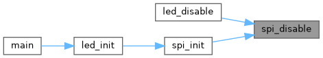
◆ spi_disable()
| void spi_disable | ( | void | ) |
Disable the SPI hardware interface and reset related pins.
This function disables the SPI peripheral on the AVR ATTiny series device by clearing the master and enable bits in the SPI control register. It also resets the SPI mode bits to their default state. The function configures the SPI-related pins (MOSI, MISO, SCK, SS) by clearing their direction bits, effectively disabling SPI pin control, and drives these pins low by clearing the output register. Additionally, the pull-up resistor on the SS pin is disabled. If SPI interrupts are enabled via the SPI_SPIE macro, this function disables SPI interrupt requests. The port multiplexer configuration for SPI is cleared and the SPI interrupt flags are reset.
- Note
- After calling this function, the SPI peripheral and associated pins are fully disabled, which is necessary before changing SPI configurations or powering down the SPI module to reduce power consumption.
◆ spi_init()
| SPI_Status spi_init | ( | SPI_Direction | direction, |
| SPI_Polarity | setup, | ||
| SPI_Phase | sample ) |
Initialize the SPI hardware interface in master mode with specified configuration.
- Parameters
-
direction Specifies the bit order for SPI data transmission (MSB or LSB first). setup Specifies the clock polarity (SPI_Polarity) to configure the clock idle state. sample Specifies the clock phase (SPI_Phase) to configure the clock sampling edge.
- Returns
- Returns an SPI_Status code indicating the result of initialization. Possible return values:
- SPI_None: Initialization completed successfully.
- SPI_Master_Abort: Initialization was aborted due to the Slave Select (SS) pin being low when SPI_ENABLE_MASTER_ABORT is enabled.
This function configures the SPI peripheral registers on the AVR ATTiny series device to initialize the SPI bus in master mode. It sets the SPI port multiplexer, configures the data direction for SPI pins, and sets up the SPI clock phase and polarity according to the specified parameters.
- Important
- If the macro SPI_ENABLE_MASTER_ABORT is defined, special handling is enabled: if during initialization the SS pin is detected low, the SPI master initialization is aborted by disabling the SPI peripheral and returning the status SPI_Master_Abort.
The function also sets pull-up resistors on the MISO and SS pins according to configuration, and configures SPI interrupts if the SPI_SPIE macro is defined.
- Note
- Ensure that the SPI pins and port multiplexer settings correspond to your hardware configuration. The function assumes a default SPI clock prescaler; customize SPI_CLOCK and SPI2X_ENABLE macros for different clock rates.
- See also
- SPI_Direction, SPI_Polarity, SPI_Phase for parameter options and configuration.
- spi_disable() for disabling the SPI peripheral in case of master abort.


◆ spi_select()
| void spi_select | ( | SPI_Select | mode | ) |
Control the SPI Slave Select (SS) pin to enable or disable the SPI slave device.
- Parameters
-
mode Specifies the SPI select state, either SPI_Enable or SPI_Disable.
This function manages the SPI Slave Select (SS) pin using the configured SPI port. When SPI_Enable is passed, the SS pin is driven low to select (activate) the SPI slave device. For any other value, the SS pin is driven high, deselecting (deactivating) the slave. This control is essential for ensuring that only one SPI slave device communicates with the master at any given time on a shared SPI bus.
- Note
- The SS pin behavior is active low; pulling it low selects the slave. Ensure that the pin configuration and port macros reflect your hardware's SPI setup.
◆ spi_transfer()
| unsigned char spi_transfer | ( | unsigned char | data | ) |
Transfer a single byte of data over the SPI bus.
- Parameters
-
data The byte value to be sent via SPI.
- Returns
- Returns the byte received simultaneously from the SPI slave device.
This function writes the provided data byte to the SPI data register, initiating the SPI transmission. It then waits in a busy loop until the SPI interrupt flag indicates that the transfer is complete. Upon completion, the function reads and returns the received byte from the SPI data register. SPI communication is full-duplex, so while sending a byte, a byte is received simultaneously. This function therefore effectively performs a combined send/receive operation.
- Note
- This is a blocking call that waits until the SPI hardware signals transmission completion. Ensure SPI is properly initialized before calling this function.